
What a Boring Log Actually Contains
A boring log is the primary field document produced during a subsurface investigation. It records, in depth order, every piece of information collected as a drill rig advances a borehole: sample recovery, blow counts, soil description, stratum boundaries, and groundwater observations. Reading one correctly requires knowing the conventions each column follows, because the symbols and numbers are shorthand for geotechnical behavior, not just visual description.
The document is typically organized in vertical columns moving left to right: depth in feet, sample type and number, blow counts, a graphic soil profile, the written soil description, and remarks about drilling conditions or water. Some logs add columns for moisture content or Atterberg limit results when those tests were run on recovered samples in the laboratory. The ASTM D2487 soil classification standard governs how each material is ultimately named and symbolized, so that same convention applies whether the boring was drilled in Houston, Dallas, or anywhere else using the Unified Soil Classification System (USCS).
Before you interpret any single line on the log, scan the header block. It records the boring location and surface elevation, the date drilled, the drilling method, and the hammer weight and drop used for SPT sampling. Those details matter because they set the context for every N-value on the page. A different hammer type or an uncalibrated energy ratio can shift N-values by 20 percent or more, which is why our geotechnical services always document hammer efficiency alongside the raw blow counts.
Understanding Soil Classification Symbols Under ASTM D2487
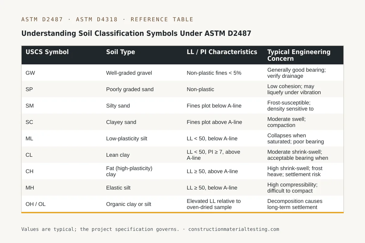
The Unified Soil Classification System assigns every soil a two-letter symbol. The first letter identifies the primary soil type: G for gravel, S for sand, M for silt, C for clay, O for organic, and Pt for peat. The second letter qualifies that type: W for well-graded, P for poorly graded, M for silty fines, C for clayey fines, L for low plasticity, and H for high plasticity. Those combinations produce the symbols you see repeated down the graphic log column.
Coarse-grained soils—GW, GP, GM, GC, SW, SP, SM, SC—are classified primarily by their grain-size distribution. Our laboratory runs ASTM D6913 sieve analysis on these materials to determine gradation coefficients (Cu and Cc), which then place the soil on the W or P branch. For the fines-bearing members like SM or SC, the plasticity of those fines also plays a role, requiring Atterberg limits testing under ASTM D4318.
Fine-grained soils—ML, CL, MH, CH, and OL/OH—are classified almost entirely by plasticity. A CL (lean clay) has a liquid limit below 50 and plots above the A-line on the Casagrande plasticity chart. A CH (fat clay) also plots above the A-line but with a liquid limit at or above 50. That single distinction—CL versus CH—carries real consequences on a boring log: CH soils in the Gulf Coast region are frequently expansive, meaning footings bearing into them without sufficient dead load or a grade beam can heave seasonally.
| USCS Symbol | Soil Type | LL / PI Characteristics | Typical Engineering Concern |
|---|---|---|---|
| GW | Well-graded gravel | Non-plastic fines < 5% | Generally good bearing; verify drainage |
| SP | Poorly graded sand | Non-plastic | Low cohesion; may liquefy under vibration |
| SM | Silty sand | Fines plot below A-line | Frost-susceptible; density sensitive to moisture |
| SC | Clayey sand | Fines plot above A-line | Moderate swell; compaction moisture-critical |
| ML | Low-plasticity silt | LL < 50, below A-line | Collapses when saturated; poor bearing wet |
| CL | Lean clay | LL < 50, PI ≥ 7, above A-line | Moderate shrink-swell; acceptable bearing when stiff |
| CH | Fat (high-plasticity) clay | LL ≥ 50, above A-line | High shrink-swell; frost heave; settlement risk |
| MH | Elastic silt | LL ≥ 50, below A-line | High compressibility; difficult to compact |
| OH / OL | Organic clay or silt | Elevated LL relative to oven-dried sample | Decomposition causes long-term settlement |
| Pt | Peat | Very high LL; fibrous | No structural bearing capacity; must be removed |
Reading N-Values and What They Tell You About Bearing
The Standard Penetration Test (SPT) drives a split-spoon sampler 18 inches into the soil below the cleaned borehole bottom using a 140-pound hammer falling 30 inches. The technician counts and records blows for each of three successive 6-inch intervals. The N-value—often called the blow count—is the sum of the second and third intervals only. The first 6-inch interval is discarded as a seating drive because it penetrates disturbed soil at the base of the casing.
On the log, you will see blow counts written as a fraction or a stack: 4/8/9 means 4 blows for the first 6 inches, 8 for the second, and 9 for the third. The reported N is 17. A low N-value—say, below 4 in a clay or below 10 in a sand—signals a soft or loose stratum. Very high counts, sometimes recorded as 50/2" (50 blows for only 2 inches of penetration), indicate refusal on rock or hardpan and terminate that sample attempt. Reviewing the N-value trend with depth is more informative than any single number: a stiff crust over soft material is a classic sign of a clay profile that could consolidate under foundation load.
For design purposes, structural engineers and geotechnical engineers correlate N-values with undrained shear strength in clays and with friction angle in sands. Those correlations appear in the geotechnical report, not on the raw boring log. Your job reading the log is to flag anomalies: a sudden drop in N-value mid-stratum may indicate a lens of weaker material, a change in mineralogy, or a water-bearing seam that softened the sample before the drive was complete.
Locating and Interpreting Groundwater on the Log
Groundwater is noted in two ways. First, the driller marks the depth at which water entered the borehole during drilling—called the 'water during drilling' or 'WDD' depth. Second, after the rig pulls the casing or at a timed interval after drilling, the technician measures the stabilized water level. Both depths appear in the remarks column or in a dedicated groundwater block on the log header. The stabilized reading is more meaningful for design because it reflects actual hydrostatic conditions, but it requires time—sometimes 24 hours or more in low-permeability clays—for water to equilibrate.
In the Houston–Gulf Coast region, perched water tables are common in the upper CL and CH deposits that blanket much of the coastal plain. A boring drilled in the dry season may show water at 8 feet, while the same stratum intercepts water at 4 feet after a wet fall. This variability means the geotechnical engineer will usually note a seasonal range in the report rather than a fixed design elevation. When you read the log, look at what USCS stratum the water table falls within—water in a CH clay behaves very differently from water in an SP sand immediately beneath it.
For footing design, the critical question is whether the groundwater elevation falls within the depth of influence below the bearing elevation (roughly 1.5 to 2 times the footing width for shallow foundations). When it does, the effective overburden stress below the footing is reduced by the buoyant unit weight of the soil, which can meaningfully lower the allowable bearing capacity calculated from those N-values. Your structural or geotechnical engineer accounts for this, but reading the log yourself helps you anticipate the conversation before the report arrives.
CH vs. CL: Why the Plasticity Distinction Controls Footing and Fill Decisions
The difference between a CL and a CH boring log entry is not cosmetic. In the Texas Gulf Coast, CH clays are the primary driver of foundation movement in residential and light commercial construction. These soils absorb water and expand, then shrink and crack as they dry. A bearing stratum marked CH through the first 10 to 15 feet of a boring is a signal that drilled piers extended to a more stable depth—or a post-tensioned slab with adequate stiffness—may be appropriate, whereas a spread footing bearing in that zone requires a careful look at the geotechnical engineer's recommended embedment and pressure.
The laboratory confirms the CL/CH call by running liquid limit and plastic limit tests per ASTM D4318 on tube samples or bulk samples recovered from the SPT split spoon. The plasticity index (PI = LL − PL) and the liquid limit together locate the soil on the Casagrande chart. If the plotted point falls above the A-line and the liquid limit is 50 or greater, the classification is CH. Our laboratory's work on these samples feeds directly into the USCS symbol on the log you receive. You can also view the full classification method in our ASTM D2487 test method page.
For fill operations, CH material recovered from on-site excavation is almost always problematic as structural fill beneath slabs or pavements. Its shrink-swell behavior causes long-term volume change that compaction alone cannot remedy. CL material at moderate plasticity may be acceptable as fill when compacted within a specified moisture window—typically within 2 percent of optimum—but that decision belongs in the geotechnical report. Reading the boring log helps the contractor understand why the specifications may call for imported select fill even when substantial cut material is available on site.
Moving Through the Log Depth by Depth: A Technician's Reading Sequence
Start at the surface and move down, noting stratum changes. Each change in the graphic log—a different pattern or hatch, a horizontal line, a new USCS symbol—marks a boundary. Read the written description alongside the graphic; the description adds color, odor notes, consistency terms (soft, firm, stiff, hard for cohesive soils; loose, medium dense, dense for cohesionless), and the presence of inclusions like shell fragments, calcareous nodules, or organic matter. Consistency and relative density terms are derived from N-value ranges defined in the USCS and common practice, and they appear standardized across logs from different drillers.
Next, trace the N-values column and look for trends. A profile that runs 2/4/6, 3/5/7, 4/6/9 with depth in a clay layer is consistently soft—concerning for a structure of any significance. A profile that suddenly jumps to 18/25/30 at 15 feet while the soil description remains CH may indicate a desiccated or preconsolidated crust, or it may reflect a different mineralogy. Cross-check with the description. If the description notes 'calcareous hardpan' or 'cemented layer,' the high N-value is real but may not reflect broad bearing stratum continuity.
Finally, note recovery. The recovery column shows the length of sample actually retrieved versus the length driven. Low recovery in a cohesive soil may mean the sample fell out of the spoon during retrieval; in coarser soil, it often means the material was too loose to be retained. Poor recovery means the USCS classification for that interval is tentative—the driller's description is based on what little material was recovered, and a follow-up sample or in-situ test may be warranted before design decisions rely on that stratum.
Where Soil Classification Fits on Your Project
Boring logs and their USCS classifications are not ends in themselves. They feed the geotechnical report, which the structural engineer of record uses to set footing depths, bearing pressures, and pier lengths. For fill placement, the log identifies which native soils can be reused and which need to be replaced, information that directly affects your earthwork bid. On projects subject to special inspection under IBC Chapter 17, the geotechnical report also defines the scope of compaction testing required—what test frequency, what acceptance criteria—because those requirements vary by soil classification.
When our field desk mobilizes to a site for subsurface investigation, the boring log produced in the field and the classification confirmed in the laboratory become the foundation documents for every downstream decision. If you have a site where the subsurface conditions are undefined or where an existing report predates a change in scope, the right time to commission new borings is before design is finalized, not after footings are already sized. Submit a proposal request and describe the site conditions you already know; we will help you determine what investigation scope makes sense for your structure type and schedule.
Get our guides in your Google results
Add Construction Materials Testing as a preferred source and Google shows our guides more often when you search for testing topics.