
Why Expansive Clay Dominates Houston's Subsurface
The Houston metropolitan area sits atop one of the most expansive clay deposits in North America. The Beaumont Formation—a late Pleistocene-age sedimentary unit laid down by ancient Gulf Coast alluvial and deltaic processes—underlies virtually all of Harris, Fort Bend, Brazoria, and Galveston counties. When you dig a boring in Sugar Land, Katy, or most of unincorporated Harris County, you are almost always encountering Beaumont clay within the first few feet of native grade. The USGS maps of surficial geology for this region make it plain: there is no pocket of non-expansive native soil waiting to be found beneath the slab of a typical Houston residential or light commercial structure.
What makes Beaumont clay so problematic is its mineralogy. The dominant clay mineral is montmorillonite (smectite), a layered phyllosilicate that can absorb water molecules between its crystal layers and expand dramatically in volume—sometimes 10–15% or more by volume in a single wet-dry cycle. When rainfall is abundant, these clays swell. When drought follows, they shrink and crack. The vertical movement at the surface is not cosmetic; it translates into differential heave and settlement that can crack foundation slabs, distort door frames, rupture plumbing, and damage masonry. Understanding the soil behavior quantitatively, not just qualitatively, is the only defensible basis for foundation design.
The practical implication for construction professionals is that expansive clay in Houston is not an edge case or a worst-case scenario—it is the baseline condition. Every geotechnical investigation in this region should include index testing and, in most cases, swell testing or potential vertical rise analysis. Skipping those steps does not make the clay less expansive; it simply transfers the risk to the structure and, ultimately, to the owner.
Index Testing: Plasticity Index as the First Screen

The first quantitative tool for characterizing an expansive clay is the Atterberg limits suite—specifically the liquid limit (LL) and plastic limit (PL) from which the plasticity index (PI = LL − PL) is calculated. We perform this testing under ASTM D4318, which prescribes the cone or Casagrande cup method for liquid limit and the hand-rolling method for plastic limit. The procedure requires air-drying and processing the minus-No. 40 sieve fraction of the soil, then running the cup or fall-cone sequence at multiple moisture contents to define the LL with a curve fit rather than a single-point estimate.
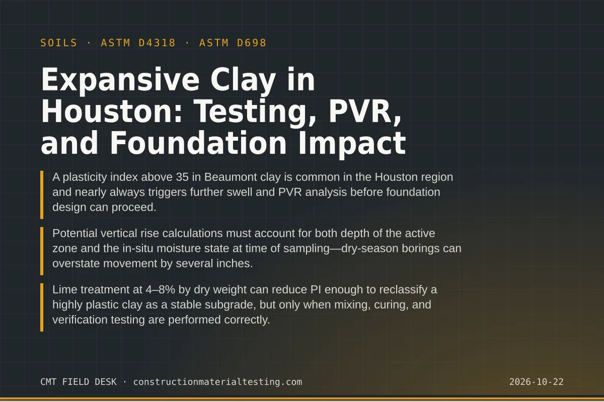
For Beaumont Formation clays, PI values in the range of 30–60 are routine. Values above 50 are not unusual in areas that have not experienced significant weathering or leaching. As a practical classification boundary, PI > 35 puts a soil firmly in the high-plasticity clay (CH) category on the Unified Soil Classification System, and at that level the potential for volume change under moisture variation is substantial. TxDOT uses PI thresholds in its pavement design specifications, and the TxDOT Standard Specifications reflect long institutional experience with these same soils. Many geotechnical engineers practicing in the Houston area use PI as a screening criterion: if PI is above about 25–30, proceed to swell testing; if PI is below that, simplified design assumptions may be acceptable depending on the structure.
One detail that matters in practice is sample handling. Beaumont clay can dry dramatically between the time it leaves the sampler and the time it reaches the laboratory. We require samples to be sealed in moisture-proof bags or tubes immediately after retrieval, logged with moisture content of the as-recovered specimen, and delivered to the laboratory without delay. A desiccated sample will still yield a valid PI, but the as-recovered moisture content—measured separately under ASTM D2216—is critical for interpreting where the soil sits relative to its shrinkage limit and for computing realistic PVR. Our geotechnical services team coordinates sampling logistics with the drilling contractor to minimize moisture loss before testing begins.
Swell Testing: Free Swell and Consolidometer Methods
Once PI flags a soil as potentially expansive, the next step is measuring swell directly. Two approaches are common in Texas practice. The free swell test (often run under ASTM D4546 Method A or B) measures the vertical strain a soil specimen undergoes when inundated at a low seating stress. This gives a percentage swell under essentially zero surcharge, which is a conservative upper bound. For foundation engineering, the more useful output is swell pressure: the stress required to prevent any volume change when the soil is wetted, or the stress at which the soil is in equilibrium at a target moisture content.
The consolidometer (oedometer) approach is the more rigorous method. A trimmed specimen—usually a 2.5-inch diameter by 1-inch-tall ring cut from a thin-walled Shelby tube—is placed in the oedometer ring under a seating load, typically 144 psf or the estimated overburden stress. The specimen is flooded with water, and the resulting swell strain is measured until equilibrium. Additional load increments are then applied to determine the swell pressure. Alternatively, the specimen can be loaded to overburden stress and flooded, measuring swelling or compression to establish the pre-consolidation stress relative to the swell pressure. Either protocol requires constant-temperature conditions and a stable, vibration-free apparatus—conditions our laboratory maintains under its documented quality system.
Edge cases arise when the in-situ moisture content is already elevated—as it often is after a wet spring—because a nearly saturated specimen may show very little swell in the lab even though the same soil, drying over summer and then rewetting the following March, will move significantly in the field. This is why some geotechnical engineers specify testing at a dried-back condition to represent the dry end of the natural moisture cycle rather than the current state. The laboratory report should always state clearly what initial moisture condition was used and what seating stress was applied; without that context, a swell percentage number is nearly impossible to interpret.
Potential Vertical Rise: Translating Lab Data to Field Movement
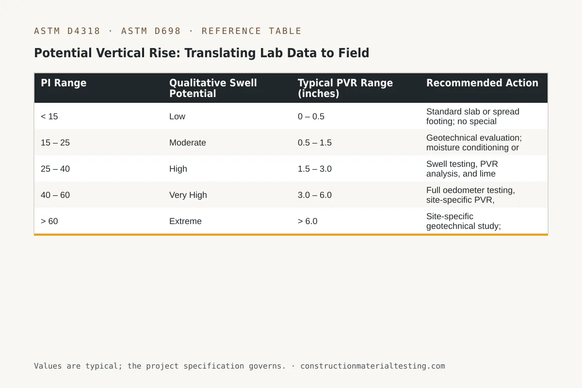
Potential vertical rise (PVR) is the calculated maximum differential or total vertical movement a soil profile could undergo if the moisture regime changed from its current state to either the driest or wettest expected condition. PVR is not measured directly; it is computed by integrating swell strains or volume-change coefficients over the depth of the active zone—the depth over which seasonal moisture fluctuations can still influence the soil. In the Houston area, the active zone typically extends from the surface to roughly 5–10 feet in open, unirrigated areas, but can be considerably shallower under well-irrigated landscaping or considerably deeper in desiccated soil adjacent to a heated building.
The Texas Department of Transportation developed a PVR computation procedure widely used in Texas residential and light commercial geotechnical practice, and it remains the standard framework for most slab-on-grade and post-tensioned slab design reports in the region. The procedure requires: (1) soil classification and PI for each stratum in the active zone, (2) in-situ moisture content relative to the soil's equilibrium moisture content, (3) surcharge or overburden at each depth increment, and (4) a volume change coefficient (often back-calculated from oedometer swell testing). The result is a PVR value in inches, which represents the estimated maximum differential movement.
PVR values in the Houston area commonly fall in the range of 1–4 inches for typical native profiles with moderate PI. Values above 4 inches are not unusual in highly active profiles with shallow groundwater or deep desiccation cracks, and values that high demand either ground improvement or significantly more robust foundation design. The structural engineer uses the PVR as a direct input to the Post-Tensioning Institute (PTI) slab design method, discussed in a later section. It is worth emphasizing that PVR is a conditional prediction: it assumes a specific change in moisture state. If the site will be well-irrigated and drainage is controlled, actual movement may be less. If a drought occurs five years after construction, actual movement could approach or exceed the computed PVR.
| PI Range | Qualitative Swell Potential | Typical PVR Range (inches) | Recommended Action |
|---|---|---|---|
| < 15 | Low | 0 – 0.5 | Standard slab or spread footing; no special treatment typically required |
| 15 – 25 | Moderate | 0.5 – 1.5 | Geotechnical evaluation; moisture conditioning or stiffened slab may be warranted |
| 25 – 40 | High | 1.5 – 3.0 | Swell testing, PVR analysis, and lime treatment or deep foundation evaluation |
| 40 – 60 | Very High | 3.0 – 6.0 | Full oedometer testing, site-specific PVR, structural slab design per PTI DC 10.5-12 or equivalent |
| > 60 | Extreme | > 6.0 | Site-specific geotechnical study; drilled pier bypass or aggressive lime/cement stabilization required |
Active Zone Depth and Moisture Conditioning in the Field
One of the most consequential decisions in a Houston geotechnical report is determining the active zone depth. Moisture movement in expansive clay is controlled by evapotranspiration at the surface, rainfall infiltration, proximity to trees (which extract moisture aggressively through root systems), and the presence of impervious cover such as slabs or pavement. A mature live oak or water oak adjacent to a slab edge can desiccate the clay to depths of 8–12 feet or more along the root pathway, creating a moisture gradient that causes differential heave when rainfall eventually restores moisture—months or years after planting.
Moisture conditioning is a construction-phase control measure designed to narrow the moisture gradient before a foundation is placed. The concept is straightforward: wet the soil in the active zone to near its equilibrium moisture content, then place the slab before significant drying can occur. In practice, conditioning is accomplished by ponding water on the stripped grade or by running irrigation lines at close spacing on the compacted subgrade and allowing the moisture to migrate downward under gravity and capillary action. The required conditioning period depends on the clay's permeability (which is low—often on the order of 10⁻⁸ to 10⁻⁷ cm/s for Beaumont clay) and the depth of the active zone. Periods of two to four weeks of continuous pre-wetting are common for residential slabs; larger commercial pads may require longer schedules.
Verification of successful moisture conditioning requires sampling and testing, not just elapsed time. We collect samples from multiple locations across the pad at multiple depths after conditioning and measure moisture content against the target specified in the geotechnical report. If portions of the pad remain below target, additional wetting is applied to those zones. Skipping the verification step is a known source of post-construction differential movement, and it is the kind of omission that becomes clear only after cracking appears. Our materials testing services team coordinates moisture verification testing with the project schedule to minimize delays between conditioning completion and slab placement.
Lime Treatment: Procedure, Mix Design, and Verification
Lime stabilization is the dominant ground improvement method for expansive clay in the Houston area, and for good reason: hydrated lime (calcium hydroxide) reacts with the clay minerals through pozzolanic and cation-exchange reactions that permanently reduce plasticity and swell potential. The pozzolanic reaction requires time—typically 28 days of curing at ambient temperature—but the ion exchange reaction (which reduces PI rapidly) happens within hours of adequate mixing. For subgrade stabilization beneath pavements and slabs, the TxDOT standard process requires pulverization of the in-situ soil to a specified depth, incorporation of lime at a specified percentage by dry weight, moisture conditioning to near optimum, compaction, and then curing under a moisture-retaining cover.
Mix design testing starts in the laboratory. We take representative bulk samples from the site, air dry, and process them through the minus-No. 4 sieve for index testing before treatment. We then prepare specimens at multiple lime percentages—typically 3%, 5%, 7%, and 9% by dry weight of soil—cure them at 60°C for 24 hours (an accelerated cure that approximates 28-day ambient curing for purposes of mix design), and run Atterberg limits on each mixture. The target is usually a PI below 20, or whatever project-specific threshold the engineer specifies. We also run ASTM D698 (Standard Proctor) compaction curves on the as-treated soil at the selected lime percentage, because lime changes the compaction curve relative to the untreated soil—the optimum moisture content shifts higher and the maximum dry density shifts lower. Using the untreated soil's compaction parameters for field density control after lime treatment will produce incorrect results.
Field verification testing during and after lime treatment is non-negotiable. Compaction is measured using nuclear density gauge or sand cone methods referenced to the treated soil's Proctor curve. After compaction and curing, additional Atterberg limits specimens are recovered from the treated layer to confirm that in-situ PI has dropped to the target range. One failure mode we encounter repeatedly is inadequate pulverization—lime cannot react with soil particles larger than about 1 inch in any meaningful timeframe, so clod size before lime application directly controls treatment effectiveness. If field PI results after curing are still elevated, the standard response is to scarify, add a supplemental lime application, re-compact, and retest.
| Lime Percentage (by dry weight) | Typical PI Reduction (CH clay) | Approximate Treated UCS at 28 days | Primary Use Case |
|---|---|---|---|
| 2 – 3% | Minimal; primarily moisture conditioning effect | < 50 psi | Temporary workability improvement only |
| 4 – 5% | Moderate; PI reduction of 15–25 points typical | 50 – 150 psi | Light pavement subgrade, pedestrian areas |
| 6 – 7% | High; PI reduction of 25–40 points typical | 150 – 300 psi | Standard subgrade stabilization for residential and light commercial |
| 8 – 9% | Very high; may achieve PI < 15 in highly plastic clay | 250 – 400 psi | Heavily loaded subgrade, significant swell suppression required |
Expansive Clay Houston Foundations: Post-Tensioned Slab Design Inputs
Post-tensioned (PT) slabs are the standard foundation system for residential and light commercial construction on expansive clay in the Houston area, and they have been for decades. The design methodology most widely used in Texas follows the Post-Tensioning Institute's DC 10.5-12 document (or its predecessor editions), which uses a ribbed or waffle-style slab stiffened by post-tensioned cables in two directions and proportioned to resist differential soil movement. The key soil input to that design is PVR—the potential vertical rise computed from site-specific geotechnical data. The structural engineer uses PVR to set the design edge moisture variation distance (em), the differential soil movement (ym), and the allowable slab deflection limits, which in turn determine tendon size, spacing, and rib geometry.
A common disconnect we observe in the field is the use of generic or borrowed PVR values rather than site-specific data. In some cases, a builder has used a geotechnical report from a project on the same street or subdivision, reasoning that the soils must be similar. Beaumont clay is notoriously variable in its in-situ moisture state, depth to sand lenses, and degree of weathering even within short distances. A PVR computed from boring data 200 feet away may underestimate or overestimate actual site conditions meaningfully. The cost of a proper geotechnical investigation—three to five borings with laboratory testing for a typical residential lot—is small relative to the cost of foundation repair if the design inputs are wrong.
One edge case that arises on infill lots in older Houston neighborhoods is the presence of fill soil over native Beaumont clay. The fill may be poorly documented construction debris, silty sand, or even previously treated lime-stabilized material placed decades ago. In these situations, the geotechnical investigation needs to characterize both the fill and the native clay below, because the fill may not behave predictably and its contribution to or buffer against differential movement needs to be understood before PVR is calculated. Our materials testing in the Houston, Texas area team works with geotechnical engineers on these investigations regularly, and the combination of index testing, compaction verification on fill, and swell testing on native samples gives the structural engineer a complete picture.
What to Do When Post-Construction Movement Occurs
Even with proper investigation, design, and construction, some differential movement occurs on expansive clay in Houston. The question is whether the observed cracking or distortion is within the expected range for the structure's design, or whether it indicates a condition outside of what was anticipated. The first step in any post-construction evaluation is to establish whether movement is ongoing or has stabilized. That requires installing benchmarks—survey monuments or settlement plates—and monitoring them over multiple seasonal cycles, at minimum one full year from wet season to dry.
If monitoring confirms ongoing heave or settlement, the next step is targeted soil investigation: borings adjacent to the distressed zones, moisture content profiles compared to the original baseline, and in some cases additional swell or PI testing to check whether the soil profile has changed (for example, if a broken irrigation line has been wetting one zone of the slab perimeter disproportionately). The cause is almost always a moisture imbalance, and identifying the moisture source—whether it is plumbing, landscaping, drainage patterns, or natural variation—is prerequisite to any repair strategy.
Repair options range from targeted re-leveling using mudjacking or polyurethane foam injection (for minor cases) to underpinning with drilled piers that extend below the active zone. Pier underpinning is effective at stabilizing a foundation against future heave only if the piers reach a depth where moisture fluctuation does not occur—in the Houston area, that typically means drilled piers 15–25 feet deep depending on local active zone depth, with bell enlargements to resist uplift forces from swelling clay acting on the pier shaft. Specifying that depth without site-specific data is guesswork. Our geotechnical services can support both the investigation and the verification testing during remedial pier installation.
Regional Variation: Sugar Land, Katy, and the Western Suburbs
The Beaumont Formation clay that underlies Harris County continues westward into Fort Bend County with similar mineral character but some variation in depth, overburden, and weathering history. In the Sugar Land and Missouri City areas, Beaumont clay often begins within 6 inches of finished grade in areas that have not been graded, and PI values in the 40–55 range are common in virgin profiles. The water table tends to be shallower in these areas than in some parts of western Harris County, which moderates the desiccation depth but also means that swelling potential is closer to being realized at all times—there is less dry-side buffer for moisture conditioning to exploit.
In the Katy area and along the I-10 corridor west of the Barker Reservoir, the stratigraphy is more variable. Sandy lenses and interbedded silts from paleo-channel deposits interrupt the clay profile in some locations, providing natural drainage pathways that can alter moisture movement significantly compared to a uniform clay profile. Geotechnical investigations in this area benefit from careful boring log interpretation and, in some cases, permeability testing to understand how moisture moves vertically through the profile. Our materials testing services in Katy, TX and Sugar Land, TX teams are dispatched from locations that allow prompt sample delivery to the laboratory, which is important for preserving in-situ moisture content in retrieved specimens.
Contractors who work across the Houston region sometimes assume that what they learned in one area applies uniformly elsewhere. It generally does not. A subcontractor who has conditioned subgrade successfully in Pearland may find that a Katy site with sandier interbeds loses moisture much faster during conditioning and requires more aggressive irrigation to maintain the target moisture front. Conversely, a site with very high natural moisture content in Fort Bend County may require less pre-wetting but greater attention to surface drainage control during construction to prevent over-saturation, which can reduce bearing capacity and complicate compaction. Site-specific data from ASTM D4318 plasticity index testing and moisture content profiles is the only reliable basis for these decisions.
Summary of Key Tests and Their Project Roles
Pulling the testing workflow together: a typical geotechnical investigation for a structure on expansive clay in the Houston region moves through several distinct phases, each producing data that informs the next decision. Index testing establishes the character of the soil and triggers further testing. Swell testing quantifies the volume-change behavior under controlled conditions. PVR computation translates laboratory data into a design number for the structural engineer. Compaction and lime-treatment mix design testing establish the parameters for ground improvement. Field verification testing during construction confirms that the treated subgrade meets design assumptions. And post-construction monitoring, if specified, provides an early warning system if conditions deviate from design.
The standards that govern this work include ASTM D4318 for Atterberg limits, ASTM D4546 for swell testing, ASTM D2216 for moisture content, ASTM D698 for compaction characteristics of treated and untreated soils, and various TxDOT test methods that parallel or complement ASTM procedures for state-funded work. For projects under municipal review in Houston, Fort Bend, or Harris County, the geotechnical report and its testing documentation are typically required as part of the building permit submission for structures with post-tensioned foundations or any foundation system that departs from the local prescriptive standards.
Our laboratory and field staff operate under a documented quality system that covers sample custody, equipment calibration, technician qualification, and data review. For soils work on expansive clay, those controls matter especially because small errors in moisture content measurement or specimen preparation can produce PVR estimates that are off by an inch or more—and an inch of PVR can mean the difference between a stiffened slab that performs adequately and one that requires a significantly different tendon layout. Consistency and traceability in the testing chain are not bureaucratic requirements; they are the technical foundation that makes the design numbers defensible.
Where This Fits on Your Project
Whether you are an engineer specifying a foundation system, a general contractor managing subgrade preparation on a commercial pad, or an owner trying to understand why a geotechnical report is recommending lime treatment before your slab is placed, the expansive clay question in Houston is one that benefits from early, coordinated testing rather than reactive investigation after problems appear. Our field teams and laboratory staff work across the Houston metro and western suburbs, supporting investigations from initial boring coordination through mix design, construction verification, and post-construction monitoring. If you have questions about the testing requirements for your specific site or project type, or if you need a proposal for geotechnical laboratory or field testing services, submit a proposal request and we will respond with a testing scope tailored to your project conditions.
Get our guides in your Google results
Add Construction Materials Testing as a preferred source and Google shows our guides more often when you search for testing topics.