
Why Utility Trenches Fail — and What Testing Is Actually Preventing
Pavement settlement over a utility corridor, pipe joint separation, and sinkhole formation at curb cuts all trace back to the same root cause: inadequately compacted backfill that consolidates under traffic or saturation. Trench backfill compaction testing is not a bureaucratic checkbox — it is the only independent verification that the material placed around and above a pipe will behave like competent soil rather than a buried void waiting to collapse. When we pull a nuclear gauge reading and find 87% relative compaction where the city standard says 95%, we are catching a problem that would otherwise show up as a $40,000 pavement repair three years later.
Utility trenches present a specific geometry that makes compaction harder than open-area earthwork. The trench is narrow, the pipe is in the way, and workers are under time pressure to restore the surface and reopen the street. Those constraints push installers toward overly thick lifts, single passes with undersized equipment, and skipped compaction in the haunch zone below the pipe springline. A well-designed inspection plan accounts for all of that — not by adding bureaucracy, but by placing tests at the lifts and locations where failures actually originate.
Establishing the Baseline: Proctor Testing Before the Trench Opens
Every field compaction result is meaningless without a laboratory maximum dry density to compare it against. Before the first shovel of backfill goes into a trench, the geotechnical engineer or the project specifications should have identified the backfill material — native soil, imported granular fill, or a specified select fill — and a Standard Proctor test (ASTM D698) should be on record for that material. The test establishes the maximum dry density and optimum moisture content under standard compactive effort. Field tests are then reported as a percentage of that laboratory value.
One Proctor does not cover every material on a corridor. If the native soil type changes along the alignment, or if the contractor switches suppliers for imported fill, a new Proctor is required. We see projects where a single Proctor from one end of a long water main is being applied to completely different soil at the other end. That mismatch produces either falsely passing or falsely failing field results, and neither outcome helps the owner. Get the Proctor updated when the material changes — the cost of the laboratory test is trivial against the cost of a disputed test result. Our materials testing services include both the laboratory characterization and the field inspection program under the same scope so there is no gap between the two.
Lift Thickness and Equipment Selection Inside the Trench
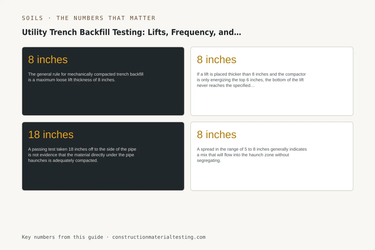
The general rule for mechanically compacted trench backfill is a maximum loose lift thickness of 8 inches. That number comes from the practical limitation of typical trench compaction equipment — a jumping jack (vibratory rammer) or a walk-behind plate compactor — to transmit compactive energy through a full depth of loose material. If a lift is placed thicker than 8 inches and the compactor is only energizing the top 6 inches, the bottom of the lift never reaches the specified density. The pipe sees uneven support, and the next lift is being placed on unstable material.
In cohesive soils or when working with materials that have a wide gradation, contractors sometimes reduce lifts to 6 inches to ensure consistent compaction through the full depth. For granular, free-draining materials like crushed stone or washed gravel used as pipe bedding, some project specifications allow up to 12-inch lifts because those materials compact more uniformly and can be verified with fewer passes. Always defer to the project geotechnical report or the city standard — those documents will specify the lift thickness for the jurisdiction and material combination, and our field technicians work from that specification, not a generic rule.
Equipment selection is as important as lift thickness. A full-size vibratory roller cannot fit in a 24-inch-wide trench. Contractors should plan for jumping jacks or plate compactors sized to the trench width. The compactor must be able to reach the full trench width without repeatedly striking the pipe or the pipe bedding — that means staggering passes and confirming coverage before moving to the next lift. Documenting the equipment type and number of passes on the field report gives the engineer of record useful context when reviewing density results.
Trench Backfill Compaction Testing Frequency: The 200–300 LF Rule
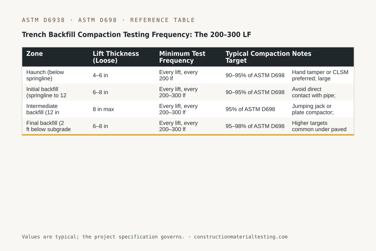
The baseline interval for trench backfill compaction testing is one test per 200 to 300 linear feet per lift. That means if a crew is placing and compacting backfill in two lifts over a 600-foot water main run, the minimum testing grid is two tests per lift at 300-foot spacing — six tests total for the run. This interval is common in Texas municipal standards and aligns with general industry practice, but it is a floor, not a ceiling. The geotechnical engineer of record may require tighter spacing in areas with poor native soils, high groundwater, or when the pipe carries a high consequence of failure such as a force main or a gas line.
Test locations should be distributed along the alignment, not clustered at convenient access points. We have seen projects where all the passing tests are near the manholes — the only spots where a truck can park close to the gauge — and the mid-run backfill was never tested. A good field technician walks the alignment and selects test locations that represent the full run, including areas where the contractor struggled with moisture control or where a pump was running to manage groundwater intrusion. Those are the spots most likely to produce a failing result, and also the spots most important to verify.
When a test fails, the protocol is to recompact the lift, add or reduce moisture as needed, and retest. The retest should not be taken immediately adjacent to the original failing test location — move at least 3 feet away so the retest reflects the corrected condition of the lift rather than the same localized problem. Two consecutive failures in the same lift at the same station should trigger a review of the compaction procedure, the moisture content, and whether the lift was placed too thick.
| Zone | Lift Thickness (Loose) | Minimum Test Frequency | Typical Compaction Target | Notes |
|---|---|---|---|---|
| Haunch (below springline) | 4–6 in | Every lift, every 200 lf | 90–95% of ASTM D698 | Hand tamper or CLSM preferred; large compactors excluded |
| Initial backfill (springline to 12 in above pipe) | 6–8 in | Every lift, every 200–300 lf | 90–95% of ASTM D698 | Avoid direct contact with pipe; no vibratory plate directly on pipe |
| Intermediate backfill (12 in above pipe to 2 ft below subgrade) | 8 in max | Every lift, every 200–300 lf | 95% of ASTM D698 | Jumping jack or plate compactor; verify equipment reaches full width |
| Final backfill (2 ft below subgrade to subgrade) | 6–8 in | Every lift, every 200–300 lf | 95–98% of ASTM D698 | Higher targets common under paved surfaces; verify city standard |
The Haunch Zone: The Hardest Lift to Compact and the Most Important to Get Right
The haunch zone is the area of backfill that runs from the bottom of the pipe to the pipe springline — roughly the lower half of the pipe circumference. It is the zone that provides structural support to the pipe against live load deflection, and it is the zone where mechanical compaction is most restricted because placing a jumping jack directly against the side of a pipe can damage the pipe wall or its protective coating. Hand tamping in the haunch zone is the traditional answer, but hand tamping is slow, inconsistent, and difficult to verify with a nuclear gauge in a tight space.
Because of those constraints, the haunch zone is where CLSM — controlled low-strength material, also called flowable fill — provides its clearest practical advantage. When flowable fill is placed in the haunch zone and allowed to flow around the pipe, it self-consolidates without any mechanical compaction effort. The material fills the void completely, including the underside of the pipe, which is nearly impossible to compact mechanically. The result is uniform support that mechanical methods rarely achieve. Our technicians confirm haunch zone placement by watching the flowable fill rise symmetrically on both sides of the pipe — if it rises faster on one side, the other side may have a blockage or a void that needs attention before the material sets.
When a contractor insists on mechanical compaction in the haunch zone, we require testing at the same 200-foot frequency as upper lifts, and we pay attention to test location. A passing test taken 18 inches off to the side of the pipe is not evidence that the material directly under the pipe haunches is adequately compacted. If the geometry does not allow us to place the gauge near the pipe, we note that in the report and recommend CLSM for that zone on future projects.
CLSM as an Alternative: What Changes in the Inspection Program
Controlled low-strength material eliminates the need for lift-by-lift density testing, but it does not eliminate the need for inspection. The inspection program shifts from field compaction testing to mix design verification, flow testing, and strength confirmation. CLSM is typically proportioned to achieve an unconfined compressive strength between 50 and 150 psi at 28 days — strong enough to support the pipe and resist soil pressure, but weak enough that future utility crews can excavate it with conventional equipment without jackhammers. Exceeding the upper strength limit is a real risk if the cement content is not controlled, and concrete that is too strong creates exactly the excavation problem you were trying to avoid.
City standards in Texas vary on CLSM acceptance. Some municipalities allow flowable fill throughout the entire trench profile; others restrict it to the haunch zone or require native soil backfill above a certain depth to match the surrounding subgrade support conditions. Before specifying CLSM on a project, confirm the city's current standard — these requirements change more often than published standard specifications. TxDOT standard specifications provide a reference framework for CLSM mix design and use on state-maintained roads, and many municipalities adopt or adapt those provisions.
Field flow testing for CLSM typically follows ASTM D6103, which measures the spread diameter of a fresh sample. A spread in the range of 5 to 8 inches generally indicates a mix that will flow into the haunch zone without segregating. We document the flow test result and the batch ticket for each truckload — truckload-to-truckload consistency matters because a mix that gets progressively wetter through the day will behave differently in the trench. Our nuclear gauge procedure under ASTM D6938 is not applicable to fresh CLSM, but we use it to verify the surrounding native soil conditions before and after flowable fill placement.
Where This Fits on Your Project
Whether you are managing a municipal water main replacement, a private utility corridor for a new development, or an emergency repair under a paved road, the inspection program for trench backfill should be defined before the trench opens — not improvised once backfill is being placed. That means a confirmed Proctor for each material, a testing frequency that matches the city standard or the geotechnical engineer's recommendation, a clear plan for the haunch zone, and a decision on whether CLSM is appropriate for the project. Our field technicians work from dispatch hubs across 27 regional locations and can support both phased utility construction and emergency response corridors.
If you are preparing a special inspection plan or coordinating with a public works department on testing frequency requirements, request a project proposal and we will review the applicable city standard, the geotechnical report, and the pipe material to develop a realistic testing scope. Getting that scope right from the start is considerably cheaper than disputing a failing test result — or a pavement failure — after the trench is closed.
Get our guides in your Google results
Add Construction Materials Testing as a preferred source and Google shows our guides more often when you search for testing topics.