

What Geotechnical Engineering Actually Is
Geotechnical engineering is the branch of civil engineering that characterizes the mechanical behavior of soil and rock and translates that behavior into design parameters for foundations, retaining systems, slopes, and earthwork. Every structure transfers load to the ground. Geotechnical engineering is the discipline that determines whether the ground can carry that load, how much it will move when it does, and how long that movement will take. Without it, foundation design is guesswork.
The discipline rests on two interlocked bodies of theory: soil mechanics and rock mechanics. Soil mechanics, formalized by Karl Terzaghi in the early twentieth century, treats soil as a three-phase material — solid particles, water, and air — and describes how the interaction of those phases governs strength, compressibility, and hydraulic behavior. Rock mechanics extends similar thinking to intact rock and rock masses, which matter most in deep drilled shafts, cut slopes in bedrock, and tunneling. Along the Gulf Coast, rock mechanics rarely governs typical building projects; soil mechanics dominates, and within that, the behavior of soft to stiff cohesive clays is usually the controlling condition.
Geotechnical engineering feeds every downstream design discipline. The structural engineer needs allowable bearing pressures and modulus of subgrade reaction to size footings and slabs. The civil engineer needs compaction specifications and subgrade CBR values to design pavements. The contractor needs excavation recommendations and dewatering guidance to build safely and on schedule. A well-executed geotechnical program compresses RFI cycles, reduces change orders, and eliminates the most expensive surprises a project can face — the ones underground.
Soil and Rock Mechanics in Plain Terms
Soil strength is not a fixed property. It depends on how fast you load the soil, whether drainage can occur, and how much normal stress the particles carry directly — a concept called effective stress. The effective stress principle, attributed to Terzaghi, states that the stress governing soil behavior is the total applied stress minus the pore water pressure in the voids. When you pile fill quickly over a saturated clay, the total stress rises immediately but the pore pressure rises with it, so the effective stress — and therefore the shear strength — barely changes until the excess pore pressure drains. This is why embankments built too fast on soft clay fail, and why the rate of construction matters as much as the load itself.
Cohesive soils, the silts and clays that make up most of the near-surface stratigraphy in the greater Houston area, derive their strength primarily from cohesion — interparticle electrostatic and cementation forces — rather than from friction between grains. Granular soils — sands and gravels — derive their strength almost entirely from internal friction, which depends on the confining stress and particle angularity. Cohesive soils are also compressible in a time-dependent way called consolidation: when effective stress increases, water slowly expels from the voids and the skeleton compresses. Sandy soils drain quickly and consolidate almost instantly under construction loads; clays can take months to years depending on their thickness and drainage boundary conditions.
Rock mechanics introduces the concept of discontinuities — joints, bedding planes, faults, and shear zones — that usually control the behavior of a rock mass more than the intact rock strength does. In South Texas where limestone or chalk underlies shallow soil, the spacing and orientation of fractures determine whether a drilled shaft can develop the side friction and tip resistance the designer assumes. We log rock core with the same rigor we apply to soil samples, recording rock quality designation and the nature of each discontinuity, because a core recovery of eighty percent looks very different depending on whether the lost twenty percent was broken at a single fracture plane or pulverized across the entire run.
The Site Investigation Sequence
A geotechnical site investigation typically runs in three phases: a desk study, a field program, and a laboratory program. The desk study reviews existing information — USGS geological maps, NRCS Web Soil Survey data, historical aerial photographs, previous geotechnical reports for adjacent parcels, and FEMA flood mapping. The goal is to identify likely stratigraphy, known problem conditions such as organic deposits or fill, and preliminary groundwater expectations before a single boring is drilled. A good desk study also identifies site-specific hazards: proximity to known fault traces, abandoned underground storage tanks, and historic landfill areas that do not always appear on current records.
The field program for a typical commercial or industrial building project consists of soil borings advanced by rotary wash or continuous-flight hollow-stem auger methods, supplemented by in-situ testing. Boring depth and spacing are governed by the expected foundation type and column loads, with guidance from ASCE 7 and project-specific engineering judgment. The ASCE Geo-Institute publishes practice guidelines that many geotechnical engineers use as a starting framework. Standard penetration testing — the SPT blow count reported as N-value — is performed at regular intervals and at every stratum change. Thin-walled Shelby tube samples are recovered from cohesive strata for undisturbed laboratory testing. In-situ cone penetrometer testing is increasingly common because the continuous log it produces resolves thin lenses that discrete SPT intervals can miss.
The laboratory program converts recovered samples into the design parameters the geotechnical engineer will use. Index testing — moisture content, Atterberg limits, grain-size analysis — classifies each stratum using ASTM D2487, the Unified Soil Classification System. Strength testing — unconfined compression, consolidated-undrained triaxial, or direct shear — quantifies the shear strength parameters. Consolidation testing on undisturbed tube samples determines the compressibility parameters needed to calculate settlement magnitude and rate. Swell-shrink testing on expansive clays quantifies the volume change potential that drives slab-on-grade and pavement distress in the Houston area.
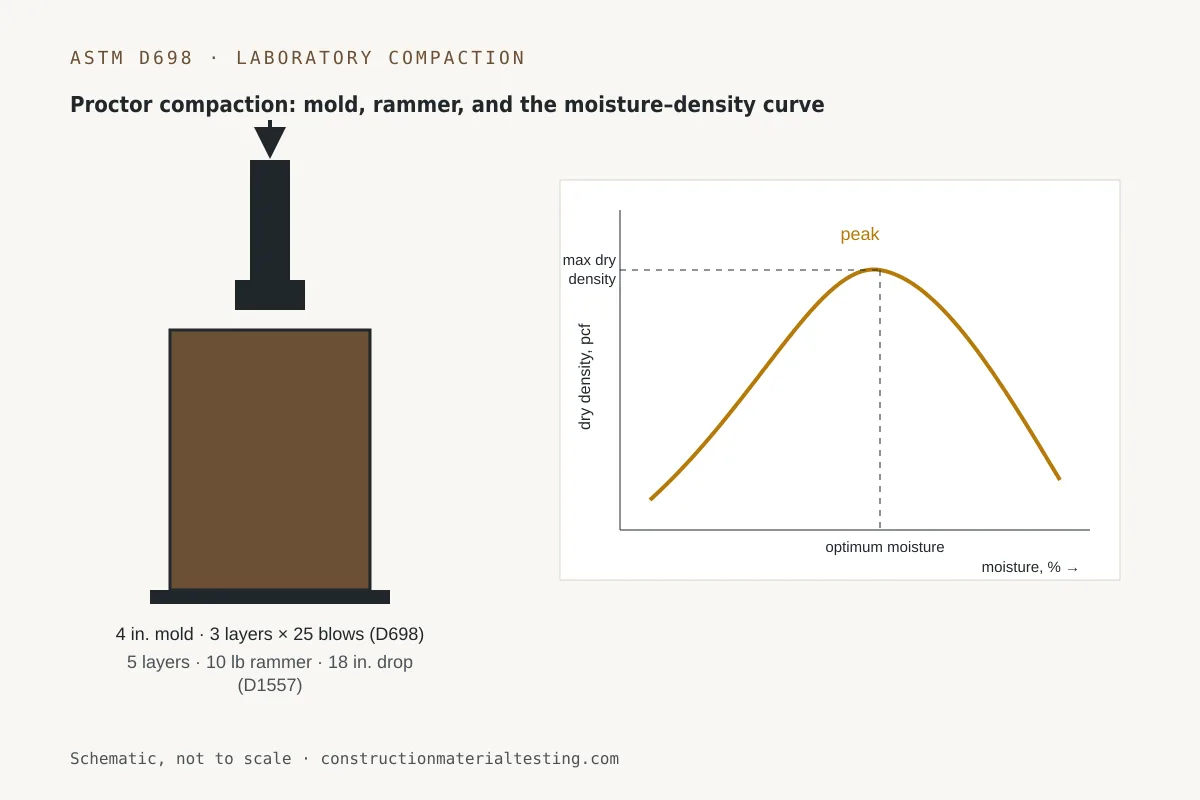
Our laboratory performs the index classification tests that feed directly into the geotechnical engineer's analysis. ASTM D4318 Atterberg limit testing — liquid limit and plastic limit — defines the plasticity index, which correlates to clay mineralogy, compressibility, and swell potential. ASTM D2487 soil classification assigns the USCS group symbol that appears on every boring log and becomes the common language between lab, field, and design. ASTM D698 Standard Proctor testing establishes the maximum dry density and optimum moisture content that earthwork specifications and compaction inspection are written around. Without accurate laboratory data, the geotechnical report is built on assumption rather than measurement.
Bearing Capacity and Settlement: The Numbers That Drive Foundation Design
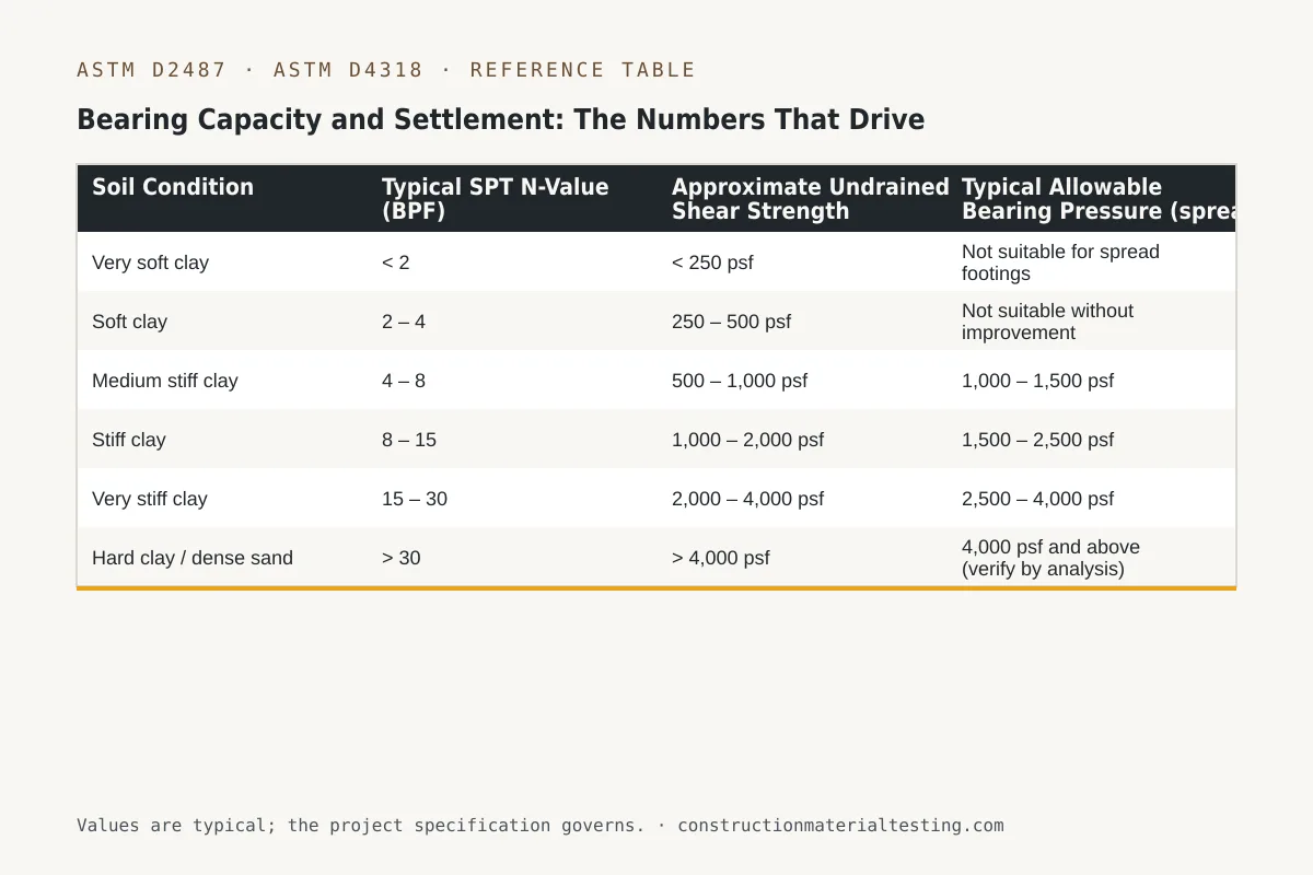
Bearing capacity is the maximum contact stress a soil can sustain without shear failure. Geotechnical engineers calculate it using closed-form solutions derived from limit-equilibrium theory — the most widely applied being the Terzaghi and Meyerhof bearing capacity equations — and they then apply a factor of safety, typically 2.5 to 3.0 for conventional foundations, to arrive at the allowable bearing pressure reported in the geotechnical report. The allowable value is what the structural engineer uses to proportion footings. In Gulf Coast soils, the allowable bearing pressure for a spread footing on stiff to very stiff native clay commonly falls in the range of 1,500 to 3,000 psf, though the actual value is site-specific and cannot be taken from a table without field and laboratory data to back it up.
Settlement analysis is often more controlling than bearing capacity for lightly loaded structures on compressible soils. Settlement has two components: immediate (elastic) settlement that occurs essentially as the load is applied, and consolidation settlement that occurs as excess pore water pressure dissipates and the clay skeleton compresses. The consolidation settlement calculation requires knowing the preconsolidation pressure — the maximum past effective stress the soil has experienced. Soils loaded beyond their preconsolidation pressure (normally consolidated clays) are far more compressible than overconsolidated clays that have been more heavily loaded in the past. The ratio of preconsolidation pressure to current effective overburden stress is the overconsolidation ratio, a key parameter that comes directly from consolidation testing on undisturbed tube samples.
Differential settlement — uneven settlement across a structure's footprint — is typically more damaging than total settlement. A building that settles uniformly by two inches usually functions without distress. A building that settles three inches at one corner and half an inch at another develops angular distortion that cracks walls, racks door frames, and can damage mechanical and utility connections. The geotechnical report should address both total and differential settlement, and the foundation design should be proportioned so that differential settlement stays within the structural system's tolerance.
| Soil Condition | Typical SPT N-Value (BPF) | Approximate Undrained Shear Strength | Typical Allowable Bearing Pressure (spread footing) |
|---|---|---|---|
| Very soft clay | < 2 | < 250 psf | Not suitable for spread footings |
| Soft clay | 2 – 4 | 250 – 500 psf | Not suitable without improvement |
| Medium stiff clay | 4 – 8 | 500 – 1,000 psf | 1,000 – 1,500 psf |
| Stiff clay | 8 – 15 | 1,000 – 2,000 psf | 1,500 – 2,500 psf |
| Very stiff clay | 15 – 30 | 2,000 – 4,000 psf | 2,500 – 4,000 psf |
| Hard clay / dense sand | > 30 | > 4,000 psf | 4,000 psf and above (verify by analysis) |
Gulf Coast Clay Realities Every Project Team Should Know
The Texas Gulf Coast is underlain by thick sequences of Pleistocene and Holocene deltaic and lacustrine clays — the Beaumont Formation being the most significant near-surface unit across a broad region including metropolitan Houston and its surrounding counties. These soils are highly plastic, frequently exhibiting liquid limits above 60 and plasticity indices above 40. By ASTM D2487, they classify predominantly as CH — fat clay — the most expansive and compressible group in the Unified Soil Classification System. The practical implication is that nearly every building, pavement, and utility system in this region sits on or in a material that swells when it wets and shrinks when it dries, sometimes dramatically.
Expansive clay movement in Southeast Texas is seasonal and can be deep. During drought conditions, the active zone — the depth over which moisture fluctuation occurs — can extend six to ten feet below grade or more depending on vegetation, drainage, and site history. A slab-on-grade or shallow spread footing that is not designed for this movement will crack. The standard geotechnical response in this region is to recommend pier-and-beam foundations with adequate crawl space, post-tensioned slabs designed to the PTI method using site-specific swell potential data, or drilled piers that extend below the active zone and are detailed with void forms or structural fill to isolate the pier cap from swelling soil. The choice depends on the structure type and the quantified swell potential from testing.
Subsidence from groundwater withdrawal has historically compounded settlement problems across Harris and surrounding counties. While pumping restrictions have slowed active subsidence in many areas, the legacy of prior settlement means that some sites carry residual effective stress changes that affect consolidation behavior in ways a simple SPT log will not reveal. This is one reason we advocate for undisturbed Shelby tube sampling and consolidation testing on projects where even modest differential settlement is consequential — a warehouse floor serving fork truck traffic, a manufacturing facility with precision equipment, or a hospital where utility coordination is rigid.
Groundwater in Gulf Coast sediments is typically shallow — often within five to fifteen feet of the surface — and is under artesian pressure in deeper confined aquifers. Excavations that penetrate clay layers into sand aquifers can experience upward hydraulic gradients that cause base heave or sand boil if dewatering is not planned. The geotechnical report for any project involving excavation deeper than about eight feet should address groundwater conditions explicitly and provide dewatering recommendations or at minimum a groundwater monitoring recommendation during construction.
Common Foundation Types and When Geotechnical Engineering Points to Each
Shallow foundations — spread footings and mat foundations — are appropriate when competent bearing strata exist at or near the surface, settlement estimates are within tolerance, and the net contact pressure is within the allowable bearing capacity. On Gulf Coast sites with stiff native clay at a shallow depth and modest column loads, spread footings are entirely viable and cost-effective. A continuous wall footing widened to reduce contact stress, or a mat that bridges across variable soil conditions and reduces differential settlement, are common solutions for low- to mid-rise structures.
Drilled piers — also called drilled shafts or caissons — are the most common deep foundation in the Houston area for structures that cannot tolerate the movement of shallow foundations or where near-surface soils are inadequate. A drilled pier transfers load through side friction along its embedded length and through tip resistance at its base. In stiff to hard clay, side friction is often the dominant load transfer mechanism. Pier lengths in local Beaumont clay for moderate commercial loads typically range from fifteen to thirty feet, but the geotechnical engineer calculates specific values from the shear strength profile. Belled piers — with an enlarged base — are less common than they were two decades ago because straight-shaft piers with adequate length and careful construction inspection perform reliably and avoid the bell-integrity uncertainty in wet-hole conditions.
Driven pile foundations appear more frequently in heavy industrial, petrochemical, and port construction along the Gulf Coast, where loads are high and the volume of work justifies mobilizing driving equipment. Steel H-piles and open-ended pipe piles are common. The geotechnical report for a driven pile project should include wave equation analysis inputs and a pile driving analyzer monitoring recommendation so that the installation achieves the design capacity verified by dynamic testing rather than relying solely on driving formula estimates. Ground improvement methods — stone columns, dynamic compaction, surcharging with wick drains — are occasionally used to upgrade soft cohesive deposits to support lighter structures or pavements and are explicitly within the scope of a geotechnical program when a site's native soils do not support conventional foundation approaches economically.
| Foundation Type | Typical Application | Governing Geotechnical Parameter | Key Risk to Investigate |
|---|---|---|---|
| Spread footing | Low to mid-rise buildings, stiff soil at grade | Allowable bearing pressure, immediate settlement | Expansive clay movement, differential settlement |
| Mat foundation | Heavy loads, variable soil, settlement equalization | Modulus of subgrade reaction, total settlement | Edge lift from expansive clay, long-term consolidation |
| Drilled pier (straight shaft) | Most Gulf Coast commercial and industrial | Undrained shear strength, pier length, side friction | Sloughing in wet holes, void forms for swell isolation |
| Driven pile (steel H or pipe) | Heavy industrial, port, bridge substructure | Unit skin friction, end bearing, pile drivability | Setup and relaxation in clays, wave equation calibration |
| Ground improvement + shallow footing | Soft to medium soils, warehouse slabs, pavements | Pre- and post-improvement strength/compressibility | Degree of improvement uniformity, verification testing |
What a Geotechnical Engineering Report Contains — and How to Read It
A geotechnical report is not a general reference document. It is specific to the explored area, the anticipated load conditions, and the foundation types evaluated. The report opens with a project description and scope of services, followed by a description of field and laboratory methods. Boring logs appear in the appendix and are the raw record of what we encountered — stratum by stratum, with SPT blow counts, sample recovery, groundwater observations, and any unusual conditions noted in real time. Reading the boring logs before reading the narrative is good practice; the narrative interprets the logs, and having your own read of the data lets you engage more productively with the engineer's conclusions.
The engineering analysis section is where the geotechnical engineer translates raw data into design parameters. Expect to find: allowable bearing pressures for the recommended foundation type or types; estimated total and differential settlement for those pressures; recommended pier or pile lengths and estimated capacities; minimum footing dimensions and depths; groundwater levels and dewatering considerations; and earthwork recommendations covering compaction specifications, acceptable fill materials, and subgrade preparation. For expansive clay sites, there should be a section addressing slab design criteria, often referencing the PTI design methodology or local practice guidelines.
The limitations section is not boilerplate to skip. It defines the spatial extent of the investigation, acknowledges that subsurface conditions between borings are inferred rather than measured, and typically states that the recommendations apply to the loading conditions described in the report. If you change the building footprint significantly, increase column loads beyond the assumed values, or find conditions in the field that differ from the boring logs, the geotechnical engineer needs to be notified. A geotechnical report is a living document in the sense that significant design changes can invalidate its recommendations, and the geotechnical engineer of record should review and concur with any such changes before foundation design proceeds.
Special Inspection During Construction: Connecting Lab Data to Field Reality
Geotechnical engineering does not end when the report is issued. IBC Chapter 17 and ACI 318 require special inspection at foundation elements to verify that what is built matches what was designed. For drilled piers, the special inspector observes the excavation to confirm that the founding stratum matches the geotechnical report's description — correct soil classification, SPT blow count range, and absence of water or soft zones at the pier tip. If the bearing stratum at the design depth looks softer or wetter than the boring logs indicated, the call goes to the geotechnical engineer before concrete is placed, not after.
For earthwork and fill operations, the field technician compares in-place density test results — nuclear gauge or sand cone per ASTM D6938 or D1556 — against the laboratory maximum dry density from ASTM D698 Standard Proctor testing. The compaction specification, typically 95 percent of standard Proctor maximum dry density for structural fill, comes directly from the geotechnical report. Each lift of fill must pass before the next lift is placed; there are no retroactive fixes once material is covered. Our geotechnical services integrate the laboratory program and field inspection so that the Proctor curve used in the office is the same one the field technician references — a detail that seems obvious but is a common source of discrepancy when lab and field programs are fragmented across different firms.
Consistency between the geotechnical report parameters and special inspection records is not only a quality issue — it is a code compliance issue. The special inspector's daily reports and summary reports become part of the project record. When a building permit is finaled, or when a property changes hands and a Phase I or structural due diligence review is conducted, those records are scrutinized. Gaps between design assumptions and inspection records create liability exposure for everyone on the project team, including the owner.
Edge Cases and Things That Go Wrong
Unidentified fill is the most common field surprise in urban infill development. Previous structures leave behind rubble, organic debris, and poorly compacted fill that does not appear in any record. Borings spaced to typical commercial investigation standards can miss localized fill pockets. When unusual conditions are encountered during excavation — fill materials, buried wood, voids, or significantly softer soil than the boring logs predicted — the correct response is to stop, document, and call the geotechnical engineer. Proceeding on the assumption that it is a local anomaly and will probably be fine is how foundations fail.
Heave in excavations, particularly in highly plastic clays, occurs when the stress relief from excavating exceeds the soil's resistance to upward movement. In deep basement or subgrade utility excavations, the bottom of the cut can heave enough to compromise the geometry and bearing of footings placed on what the engineer assumed was undisturbed material. If excavation geometry changes during construction — the cut goes deeper or wider than planned — the geotechnical engineer should review the revised geometry before foundation elements are placed.
Liquefaction is not a Gulf Coast abstraction: saturated, loose sand or silty sand deposits in the region, while not ubiquitous, do exist in abandoned channel deposits and reworked deltaic sand lenses. Seismic hazard in Southeast Texas is low but not zero, and for critical facilities the geotechnical program should include a liquefaction assessment if SPT blow counts in any saturated sand stratum are low. The assessment requires site-specific seismic hazard data and a standard procedure analysis; it is not something to estimate from regional generalizations. Similarly, slope stability analysis for any site with grades steeper than about 3:1, or any site near a bayou or drainage channel, should be part of the geotechnical scope rather than an afterthought.
Where Geotechnical Engineering Fits on Your Project Timeline
Geotechnical engineering work needs to begin early — ideally during schematic design, before the structural system is selected and certainly before construction documents are issued. Waiting until a building permit is applied for means the structural engineer has been designing to assumed parameters that may or may not match reality. If the geotechnical report comes back with recommendations that conflict with the assumed foundation type, the redesign cost and schedule impact dwarf what the earlier investigation would have cost.
Our team mobilizes field crews from our geotechnical services division through our regional dispatch network, and laboratory turnaround on index testing supports the report schedule your design team needs. If your project is in the planning or early design phase — or if you have encountered unexpected subsurface conditions mid-construction — submit a proposal request and we will scope the investigation, turnaround, and special inspection program for your specific site and schedule.
Get our guides in your Google results
Add Construction Materials Testing as a preferred source and Google shows our guides more often when you search for testing topics.