
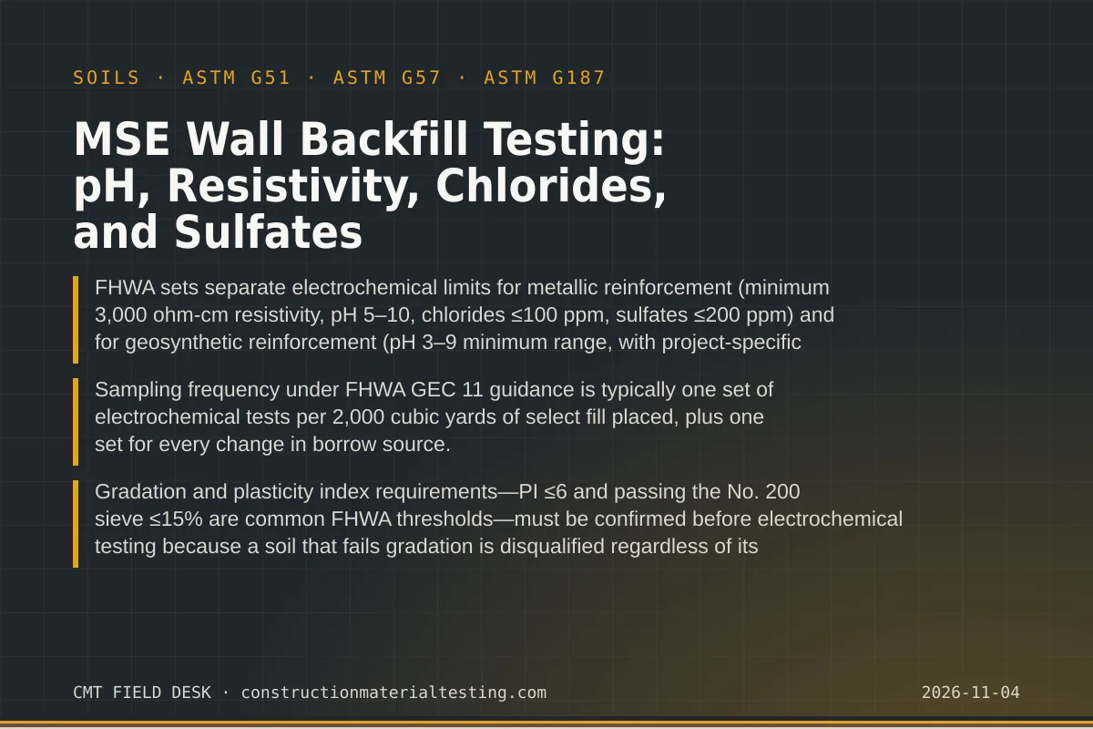
Why Backfill Chemistry Determines Wall Longevity
Mechanically stabilized earth walls depend on the long-term interaction between reinforcement elements and the surrounding fill. When that fill is chemically aggressive, it accelerates corrosion of galvanized steel strips or welded wire mats and can degrade the polymer chains in geosynthetic geogrids and geotextiles. Owners and engineers often treat MSE wall backfill testing as a paperwork exercise, but the electrochemical properties of the retained soil are the primary variable controlling design life. FHWA's design guidance recognizes this by tying reinforcement type selection and sacrificial thickness calculations directly to measured soil chemistry.
The four electrochemical parameters tested—pH, electrical resistivity, water-soluble chloride content, and water-soluble sulfate content—each attack reinforcement through a distinct mechanism. Low pH accelerates zinc consumption on galvanized elements and can hydrolyze certain polyester geosynthetics. Low resistivity indicates high ionic conductivity, which drives electrochemical corrosion cells. Chloride ions disrupt the passive oxide layer on zinc and steel. Sulfates, particularly when sulfate-reducing bacteria are present, create localized corrosion environments that concentrate attack at specific points on a strip or bar mat.
Understanding what each test measures—and what happens when a fill fails one parameter but passes others—is essential for everyone involved in wall construction: the contractor selecting and placing fill, the geotechnical engineer specifying acceptance criteria, and the special inspector running quality-control sampling in the field. This guide walks through the complete MSE wall backfill testing program from borrow evaluation to final placement documentation.
FHWA Electrochemical Limits for Metallic Reinforcement
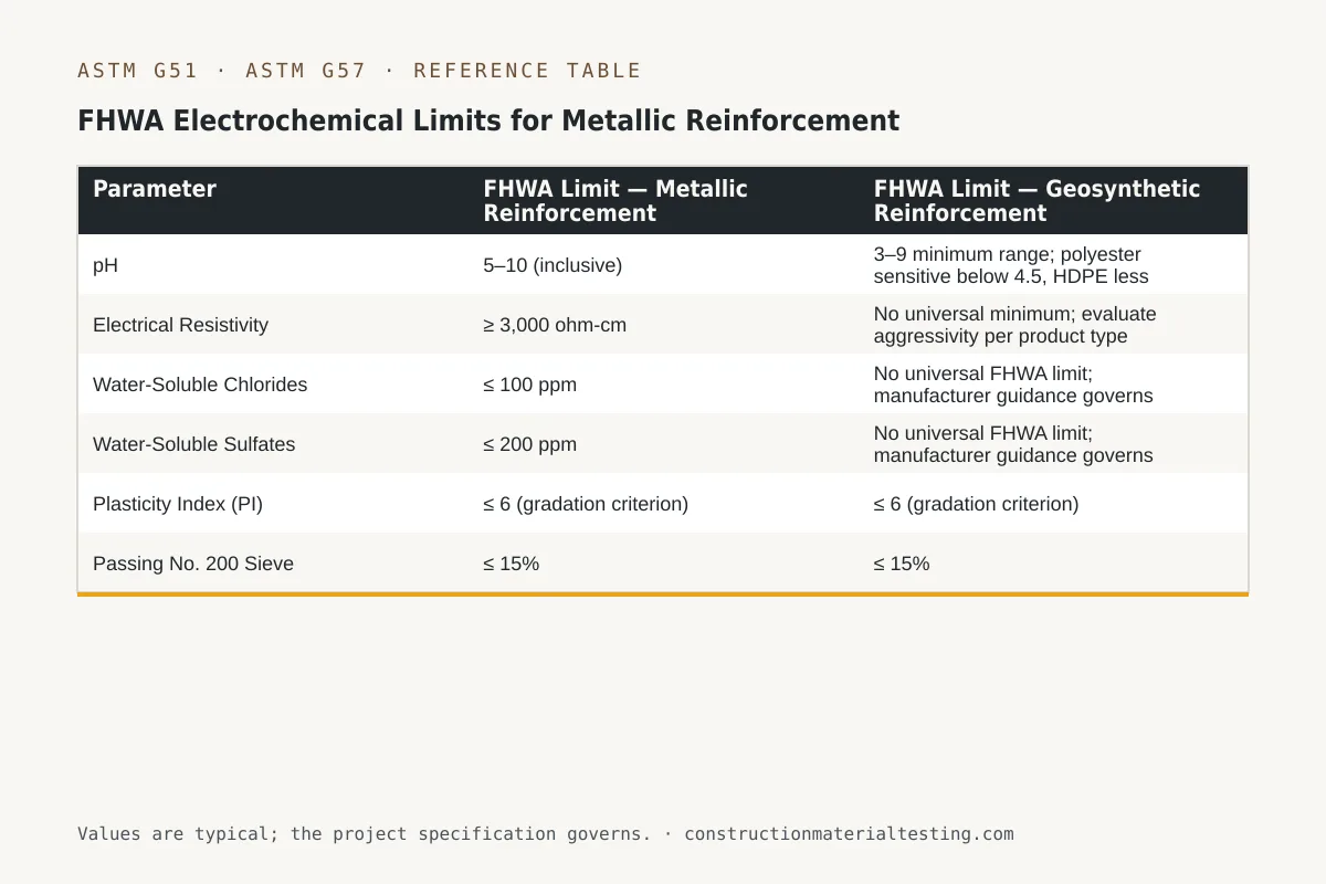
FHWA Geotechnical Engineering Circular No. 11 (FHWA GEC 11) establishes the benchmark electrochemical criteria that most state DOTs and project specifications reference when galvanized steel strips, bar mats, or welded wire reinforcement are used. The limits define what FHWA calls "electrochemically stable" fill: a soil environment in which the standard corrosion design model—based on a measured zinc loss rate and a 75- or 100-year design life—holds without additional sacrificial thickness or coatings beyond the standard galvanization.
For metallic reinforcement, FHWA's criteria require minimum soil resistivity of 3,000 ohm-centimeters, pH between 5 and 10, chloride content not exceeding 100 parts per million, and sulfate content not exceeding 200 parts per million. All four criteria must be satisfied simultaneously. A soil with resistivity of 5,000 ohm-cm and pH of 6.5 is still unacceptable if its chloride content tests at 150 ppm. The design engineer may use soils outside these limits with an adjusted corrosion model and increased sacrificial steel, but that decision rests with the engineer of record and typically requires owner approval.
Resistivity is the parameter that most often triggers re-evaluation in Gulf Coast and coastal plain projects, where native soils carry elevated salt loads from marine depositional environments. We regularly see resistivity values below 1,000 ohm-cm in dredge spoil or coastal clay mixed inadvertently into borrow. When resistivity drops below 1,500 ohm-cm, the corrosion rate model accelerates substantially, and the standard 85-micron galvanization thickness provides far less protection than the 75-year design assumes.
| Parameter | FHWA Limit — Metallic Reinforcement | FHWA Limit — Geosynthetic Reinforcement |
|---|---|---|
| pH | 5–10 (inclusive) | 3–9 minimum range; polyester sensitive below 4.5, HDPE less pH-sensitive |
| Electrical Resistivity | ≥ 3,000 ohm-cm | No universal minimum; evaluate aggressivity per product type |
| Water-Soluble Chlorides | ≤ 100 ppm | No universal FHWA limit; manufacturer guidance governs |
| Water-Soluble Sulfates | ≤ 200 ppm | No universal FHWA limit; manufacturer guidance governs |
| Plasticity Index (PI) | ≤ 6 (gradation criterion) | ≤ 6 (gradation criterion) |
| Passing No. 200 Sieve | ≤ 15% | ≤ 15% |
FHWA Considerations for Geosynthetic Reinforcement
Geosynthetic reinforcement—polyester (PET) geogrids, high-density polyethylene (HDPE) geogrids, and woven polyester geotextiles—responds to soil chemistry through polymer-specific degradation rather than electrochemical corrosion. FHWA GEC 11 and the associated product-specific installation damage and durability research do not publish a single universal electrochemical pass/fail table for geosynthetics comparable to the metallic reinforcement criteria. Instead, the guidance directs designers to evaluate pH range, oxidation potential, and the specific polymer's known durability coefficients.
Practically, most geosynthetic manufacturers provide installation damage reduction factors and durability reduction factors (RF_ID and RF_D) that assume a certain pH range and temperature. PET polyester is particularly vulnerable to hydrolysis in strongly alkaline environments—pH above 9 to 10 accelerates chain scission—and to acidic attack below pH 4 to 4.5. HDPE is more chemically inert across a broader pH range but is subject to oxidative degradation. When a project uses geosynthetic reinforcement, we always pull the manufacturer's durability documentation and confirm that the measured soil pH falls within the range the product's reduction factors assume.
Even without universal electrochemical limits, measuring pH, resistivity, chlorides, and sulfates for geosynthetic walls is still worthwhile. Highly aggressive soils may void warranty coverage, and discovering a chloride or sulfate anomaly during construction is far less costly than a post-construction investigation. Some state DOT specifications impose pH limits of 4.5 to 9 or 3 to 9 for geosynthetic fills, so always read the project specification first.
Gradation and Plasticity Index: First Gate Before Electrochemical Testing
Electrochemical testing is only meaningful on fill that meets the structural gradation requirements for MSE wall select fill. FHWA GEC 11 specifies that select granular fill must pass the No. 4 sieve at 100%, have no more than 15% passing the No. 200 sieve, and carry a plasticity index of 6 or less. Some state DOTs tighten these limits—Texas, for example, has historically specified PI ≤ 6 and may require D15 compatibility with drainage requirements. We run sieve analysis per ASTM D6913 and Atterberg limits before any electrochemical suite to avoid spending laboratory resources on a material that fails the basic structural acceptance criteria.
High fines content and elevated plasticity index are early indicators of potential electrochemical problems as well. Soils with significant clay mineral content retain moisture, hold chloride and sulfate ions in the pore water, and tend toward lower resistivity. A PI above 6 often correlates with resistivity values below 2,000 ohm-cm in our experience with Southeast Texas borrow sources. The gradation test is thus both a structural filter and a corrosion-risk screening tool.
When a borrow source shows borderline fines content—say, 12 to 15% passing No. 200—we recommend running the full electrochemical suite anyway to establish baseline chemistry before material is placed. If fines are at the upper limit and resistivity is marginal, the combination can push the corrosion model well outside the standard design envelope even if each individual parameter barely passes.
MSE Wall Backfill Testing: Sampling Frequency and Field Protocol
FHWA GEC 11 guidance calls for electrochemical testing at a frequency tied to the volume of select fill placed and to changes in borrow source. The widely adopted reference frequency is one complete set of electrochemical tests for every 2,000 cubic yards of fill, with an additional set required whenever the fill source changes—even if the new source is from the same general borrow area but a different cut or stockpile location. Project specifications sometimes increase this frequency for high-risk walls (taller walls, walls near utilities, or walls in chemically active environments).
In the field, samples for electrochemical testing should be collected from the active fill placement area, not from the stockpile surface. Stockpile weathering and leaching can alter surface chemistry. We sample from freshly exposed material at a minimum depth of six inches below the stockpile face or from the placed and lightly compacted lift before roller passes. For each set, we collect sufficient material for pH, resistivity, chloride, and sulfate tests—typically five to ten pounds of material in sealed, labeled containers with chain-of-custody documentation noting the borrow source GPS coordinates, moisture condition, and the lift elevation where the sample was taken.
Temperature at sampling matters for resistivity. Soil resistivity is inversely proportional to temperature, and field samples collected in a Texas summer will show lower resistivity than the same soil tested in winter conditions. Laboratory resistivity testing using the soil box method standardizes temperature—ASTM G187 specifies measurement at or correction to 25°C—which is why we do not rely on in-place field resistivity meters for acceptance testing. The soil box method on a prepared slurry gives reproducible results that the engineer of record can compare directly across testing events.
Test Methods: pH, Resistivity, Chlorides, and Sulfates in Detail
pH is measured per ASTM G51, which covers the determination of soil pH specifically in the context of corrosion testing. The procedure uses a 1:1 soil-to-water ratio by mass, agitated and allowed to equilibrate before electrode measurement. The 1:1 ratio matters—using a different dilution changes the measured pH, so the test report should always state the method and ratio. We calibrate pH electrodes with two-point buffer calibration bracketing the expected measurement range before every set of samples.
Resistivity is typically measured in the laboratory using the two-electrode soil box method described in ASTM G187, or by the Wenner four-electrode field method described in ASTM G57. For MSE wall acceptance testing, the soil box method on a remolded sample at or near optimum moisture content is the more common approach because it tests the material the wall will actually see—not the native in-place soil. Our ASTM G187 procedure packs the soil into a Lucite box at a specified density, saturates it, and measures resistance across the electrodes; resistivity is calculated from resistance, electrode spacing, and cross-sectional area. The ASTM G51 test for pH and the ASTM G187 resistivity test are frequently run in parallel from the same prepared sample.
Water-soluble chloride and sulfate contents are determined through aqueous extraction—soil is mixed with deionized water, filtered, and the extract is analyzed. Chlorides are typically measured by titration (Volhard or Mohr method) or ion chromatography; sulfates are commonly determined gravimetrically as barium sulfate precipitation or by ion chromatography. Results are reported in parts per million (mg/kg dry soil). The extraction ratio and the analytical method should be specified in the project's quality control plan, because different extraction ratios can produce different apparent concentrations—a detail that matters when results are near the acceptance threshold.
Our materials testing services run all four electrochemical parameters as a package, with results typically reported together so the engineer of record can evaluate the complete corrosion aggressivity profile rather than individual parameters in isolation.
Interpreting Results Near the Threshold
A test result that just misses the acceptance limit is not automatically a cause for rejection. It is a cause for investigation. When resistivity comes in at 2,800 ohm-cm against a 3,000 ohm-cm minimum, our first step is to check the sample's moisture condition relative to optimum. Soil resistivity decreases as moisture increases, so a sample collected at above-optimum moisture—common during wet weather placement—may show lower resistivity than the same material placed and compacted at the specified moisture content. Re-sampling under controlled moisture conditions, or testing at optimum moisture content in the laboratory, can resolve the discrepancy.
When pH falls slightly below 5, the first question is whether the acidic signature is uniform across the borrow area or concentrated near oxidizing sulfide minerals—iron pyrite, for example—that may be isolated pockets rather than a characteristic of the whole source. We sample from multiple locations within the suspect area, mapping results spatially. A single acidic sample from a localized pyrite seam does not necessarily disqualify the entire borrow source, but it does require selective excavation and rejection of the affected zone.
Chloride and sulfate results near threshold are particularly worth re-testing at saturated conditions rather than at optimum moisture, because FHWA's limits are defined on the basis of pore water chemistry at saturation. If sulfate content tests at 185 ppm at optimum moisture and the wall will be subjected to periodic wetting, the effective sulfate concentration in pore water during wet cycles may exceed the 200 ppm limit. Flag this scenario for the engineer of record rather than issuing a simple pass.
Any series of results with multiple parameters hovering near limits—marginal resistivity, marginal pH, and chlorides at 80 ppm—should trigger a conversation with the design engineer about whether the standard corrosion model is still appropriate or whether increased sacrificial zinc thickness or a different reinforcement type is warranted. We document all near-threshold results with the full laboratory data package, not just the final pass/fail notation.
Sampling Frequency Reference and Acceptance Summary
The table below consolidates the testing parameters, typical frequencies, and acceptance limits most commonly referenced in FHWA-aligned project specifications. Individual state DOT specifications and project-specific geotechnical reports may adjust these values, and the project specification always governs over generic guidance.
| Test | Standard | Typical Frequency | Metallic Reinforcement Limit | Common Geosynthetic Guidance |
|---|---|---|---|---|
| Sieve Analysis / Gradation | ASTM D6913 | 1 per 500 CY; every source change | ≤ 15% passing No. 200 | Same as metallic |
| Plasticity Index | ASTM D4318 | 1 per 500 CY; every source change | PI ≤ 6 | PI ≤ 6 |
| Soil pH | ASTM G51 | 1 per 2,000 CY; every source change | pH 5–10 | pH 3–9 (PET); broader for HDPE |
| Soil Resistivity | ASTM G187 (lab) or ASTM G57 (field) | 1 per 2,000 CY; every source change | ≥ 3,000 ohm-cm | No universal limit; assess aggressivity |
| Water-Soluble Chlorides | Aqueous extraction + titration or IC | 1 per 2,000 CY; every source change | ≤ 100 ppm | Per manufacturer durability documentation |
| Water-Soluble Sulfates | Aqueous extraction + gravimetric or IC | 1 per 2,000 CY; every source change | ≤ 200 ppm | Per manufacturer durability documentation |
What Happens When Fill Fails Acceptance Criteria
When a fill lot fails one or more electrochemical criteria, the contractor and engineer of record must decide among three options: reject the material and source clean fill, treat the material, or redesign the reinforcement system to accommodate more aggressive conditions. Rejection is straightforward when an alternative borrow source is readily available, but in some regions—particularly where quarried granular material is scarce and hauled fill is expensive—rejection has significant cost implications. Document the rejection with the specific test results and the sample location so the contractor can demonstrate to the owner what was placed versus what was rejected.
Treatment options exist but are limited. Lime stabilization, commonly used to reduce plasticity in subgrade soils, raises pH—which can help an acidic fill but may overshoot if pH climbs above 10, introducing a different limit violation. Blending aggressive fill with clean, granular import at a controlled ratio can bring chloride and sulfate concentrations within limits if the source material is moderately out of range, but blending requires careful re-testing at the actual blend ratio before acceptance. Never assume a 50-50 blend produces 50% of the initial concentration; soil chemistry is not strictly linear due to mineral surface interactions.
Redesigning the reinforcement system to accommodate aggressive fill is an engineering-of-record decision that may involve switching from galvanized strip to epoxy-coated or stainless-clad reinforcement, increasing sacrificial zinc thickness using FHWA's corrosion rate model for more aggressive environments, or switching to a geosynthetic reinforcement whose polymer is resistant to the specific chemical exposure. Any such change requires formal design revision and typically owner approval, so the special inspection team's role is to get accurate, well-documented test data to the engineer quickly—not to make the material substitution decision.
Documentation, Reporting, and Quality System Requirements
MSE wall electrochemical test reports must carry enough traceability information to be defensible throughout the wall's design life. At minimum, each report should identify the borrow source by GPS coordinates or station reference, the lift elevation or placement date at the time of sampling, the sample moisture condition, the laboratory test methods by ASTM designation, and the results with units. Reports that list only a pass/fail notation without the raw data provide no value for future forensic investigation if corrosion distress is observed decades later.
Our laboratory operates under a documented quality system that covers sample receipt, preparation, testing, and report issuance. Calibration records for pH meters, conductivity bridges, and analytical balances are maintained and traceable. When a re-test is requested because a result is disputed, we retain the original prepared sample for a specified hold period so the re-test can be performed on the same material under the same conditions rather than from a new field sample.
Special inspectors documenting MSE wall construction should reference the electrochemical test results in their daily field reports, noting the specific lot of fill placed and cross-referencing the laboratory report number. If fill is placed before electrochemical results are available—which sometimes happens under production pressure—the report should note this explicitly as a hold point and confirm that the engineer of record approved continued placement pending results. Placing fill and burying it before results are known is a risk management exposure, not standard practice.
Where This Fits on Your Project
MSE wall backfill testing is not a standalone task—it ties directly into the broader geotechnical quality control program for the structure. Gradation and compaction testing, settlement monitoring, and facing panel installation all depend on the fill being structurally and electrochemically acceptable before it is locked in place. We coordinate electrochemical sampling with compaction testing rounds so fill that fails chemistry can be identified and addressed before additional lifts cover it.
Whether your project is at the borrow-source evaluation stage, mid-construction, or approaching final inspection, we can mobilize technicians to collect samples, process them through our materials testing laboratory, and return results with a written summary referenced to FHWA GEC 11 and your project specification. If you need a testing plan or are evaluating a borrow source before construction begins, request a proposal and describe the wall type, reinforcement system, and estimated fill volume—we will put together a sampling frequency schedule and cost estimate aligned to your specification requirements.
Get our guides in your Google results
Add Construction Materials Testing as a preferred source and Google shows our guides more often when you search for testing topics.