
What a Nuclear Density Test Actually Measures
A nuclear density test uses two separate radioactive sources to measure two separate properties simultaneously: bulk wet density and volumetric water content. The gauge housing contains a cesium-137 source for density measurement and an americium-241/beryllium source for hydrogen detection, which serves as a proxy for water. Neither source directly tells you compaction. The gauge produces counts—photon or neutron interactions detected per unit time—and the electronics convert those counts to density and moisture readings through calibration curves built into the device.
Density is determined by gamma-ray attenuation. The cesium source emits gamma photons into the soil, and a detector on the underside of the gauge counts how many photons complete the trip. Denser material attenuates more photons, so fewer arrivals mean higher density. Water content is determined by neutron thermalization: fast neutrons collide with hydrogen atoms in water molecules, slow down, and bounce back to a detector. More returning thermal neutrons means more hydrogen, which the gauge translates to moisture by mass. Dry density is then computed as wet density minus the moisture contribution—no separate oven test required, though ASTM [D2216]( /test-methods/astm-d2216) oven drying remains the reference method when the nuclear moisture reading is in question.
The distinction between wet density, dry density, and percent compaction is where field reports most often get misread. The gauge outputs wet density and moisture content directly. Dry density is a derived value. Percent compaction is dry density expressed as a fraction of the maximum dry density established by a laboratory Proctor—ASTM D698 for standard effort or D1557 for modified effort. Until you know which Proctor curve applies, the gauge number by itself is incomplete.
Direct Transmission vs. Backscatter: Choosing the Right Mode
ASTM D6938 defines two geometric configurations for the gamma source. In direct transmission mode, the source rod is lowered into a pre-drilled hole so that gamma photons travel laterally through the soil and up to the detector on the gauge base. In backscatter mode, the rod stays retracted at the gauge surface and photons scatter back from the top few inches of material. The geometry difference is not trivial: direct transmission interrogates a cylinder of soil at the measurement depth, while backscatter is sensitive almost entirely to the top 75 to 100 mm.
For most earthwork applications—subgrade preparation, structural fill, trench backfill—direct transmission is the required mode. The rod is driven to a standard depth, typically 150 mm (6 inches) for a single-lift test, but the gauge can be set at 100, 150, 200, 250, or 300 mm depending on lift thickness and project specification. Going too shallow measures a zone that has been disturbed by the drive pin process itself; going too deep integrates material from the underlying lift. Selecting the depth to match the loose lift thickness before compaction is a judgment call that the technician must make before the roller passes.
Backscatter is appropriate when a surface cannot be penetrated—sealed asphalt, thin bonded overlays, or situations where a drive pin hole would compromise the layer being tested. Because the measurement zone is so shallow, backscatter readings are sensitive to surface texture, moisture film, and gauge-seating irregularities. If the gauge rocks even slightly, air gaps near the detector edge distort the count. Backscatter results carry more variability and should not be treated as interchangeable with direct transmission results on the same acceptance curve.
Standard Counts, Calibration, and Why They Matter Every Shift
Before any test data can be trusted, the gauge must be checked against its reference block—a block of magnesium oxide or other stable material supplied with the unit. This check produces standard counts for both the gamma and neutron detectors. ASTM D6938 requires that standard counts be taken at the beginning of each day's use, and many gauge manufacturers and quality programs tighten that to every shift or any time the gauge has been transported, thermally cycled, or subjected to a sharp impact.
Standard counts serve two purposes. First, they confirm that the detector electronics are stable. Second, they provide the baseline from which a ratio is computed for every field test—the gauge compares field counts to standard counts, not to an absolute number. If standard counts drift outside the manufacturer's acceptable band without being recorded, every test taken after the undetected drift is suspect. We log standard counts on the same data sheet as field tests so that the shift record is traceable in both directions.
Calibration of the underlying density and moisture curves is a deeper process performed by the gauge manufacturer or a qualified calibration facility, not in the field. The field technician cannot recalibrate the unit. What the technician can and must do is apply any site-specific correction factors—most commonly a moisture offset—that account for the difference between the calibration soil chemistry and the project soil. Calcium-rich soils, soils with elevated iron content, or soils with high organic matter can cause systematic moisture errors that offset the neutron response. These corrections are derived from a set of paired nuclear and oven-dry measurements taken on the project material at the beginning of work.
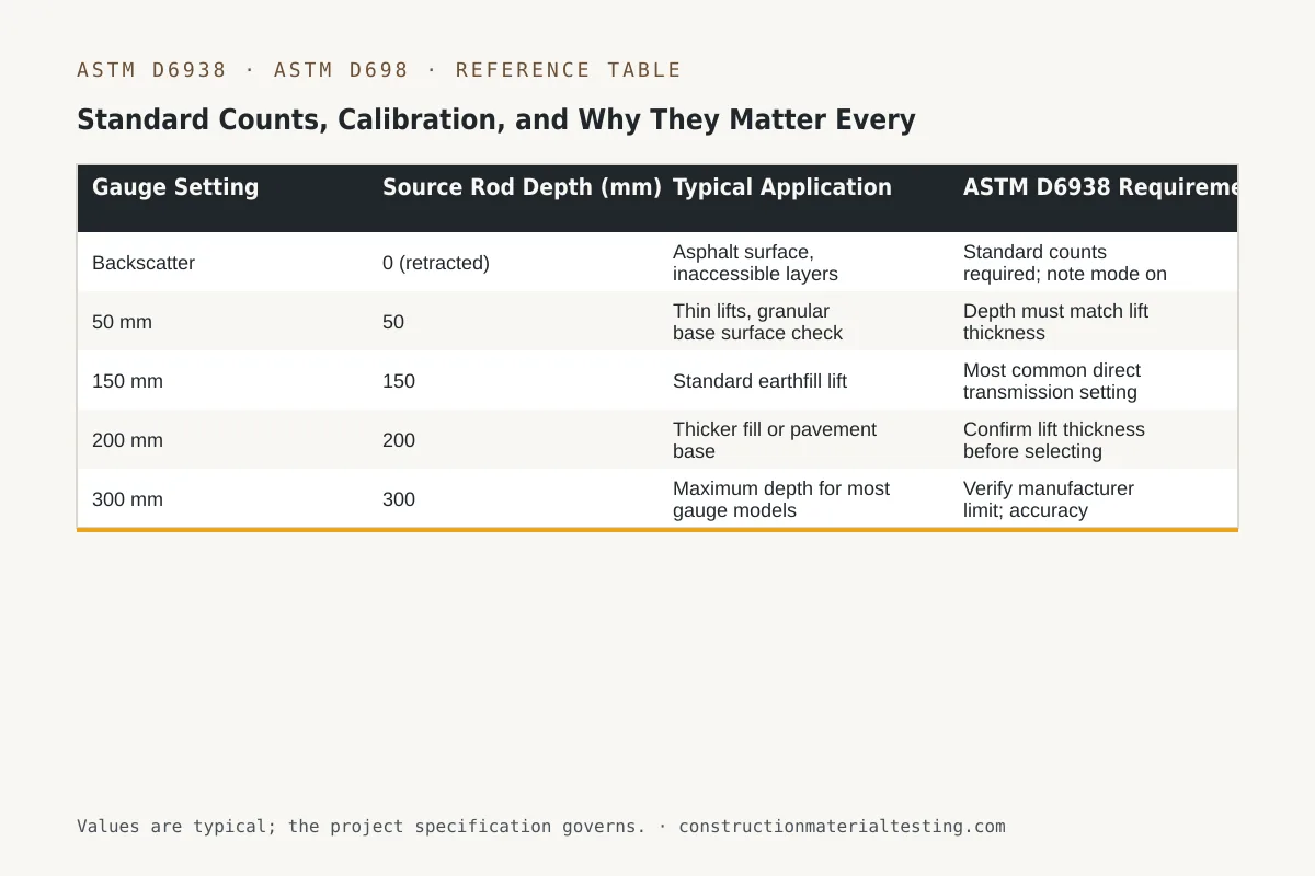
| Gauge Setting | Source Rod Depth (mm) | Typical Application | ASTM D6938 Requirement |
|---|---|---|---|
| Backscatter | 0 (retracted) | Asphalt surface, inaccessible layers | Standard counts required; note mode on report |
| 50 mm | 50 | Thin lifts, granular base surface check | Depth must match lift thickness |
| 150 mm | 150 | Standard earthfill lift | Most common direct transmission setting |
| 200 mm | 200 | Thicker fill or pavement base | Confirm lift thickness before selecting |
| 300 mm | 300 | Maximum depth for most gauge models | Verify manufacturer limit; accuracy decreases near max |
Gauge Safety and Licensing Requirements
Nuclear density gauges are portable radioactive material devices regulated under federal and state authority. In Texas, possession and use of a gauge requires a radioactive material license administered through or recognized by the Texas DSHS Radiation Control Program. The license specifies who may operate the gauge, how it must be stored and transported, what dosimetry personnel must wear, and how incidents or losses must be reported. Our technicians operate under this framework; a gauge arriving on a site without a licensed operator present is a regulatory violation, not just a safety concern.
The U.S. Nuclear Regulatory Commission provides detailed guidance on general license and specific license categories for portable gauges. Most testing firms hold a specific license because it allows broader use and greater flexibility in transport. Regardless of license type, the gauge must travel in a Type A or equivalent approved shipping case with required radiation labels, and the case must be locked when not in attended use. The source rod must be retracted and locked before moving the gauge more than a few feet.
From a practical field standpoint, technicians must wear their dosimetry badge any time the gauge is in use and must not lay the gauge on its side or store it near personnel rest areas. The annual whole-body dose limits set by regulation are not the concern in normal daily use—exposure from a properly handled gauge at working distance is low—but complacency is how small violations accumulate. Gauge safety training is not optional background knowledge; it is a prerequisite to operating the instrument, and our field technician career path builds in that training before any operator takes a gauge to the field.
Running a Nuclear Density Test: Field Procedure Step by Step
The site preparation begins before the gauge comes out of the truck. The test location should be selected in accordance with the project's special inspection plan or the engineer's specification—random selection within a defined area, not operator-chosen spots that happen to look good. The surface must be scraped level so the gauge base seats without rocking; any void under the gauge creates an air gap the detector reads as low-density material. We scrape a roughly 300-mm-square area with a hand scraper, then check for seating by pressing the gauge down with moderate hand pressure and confirming it does not tip.
For direct transmission, the drive pin is set through the guide plate at the center of the scraped area and driven to the target depth with a slide hammer. The hole is driven straight—a canted hole changes the effective measurement depth and pulls the rod against the hole wall, which can chip the source capsule over time. The drive pin is then extracted, the gauge rod is lowered into the hole to the matching depth setting, and the gauge is seated on the guide plate. Count time under ASTM D6938 is one minute minimum; most modern gauges run a one-minute count automatically and display results at the end.
The gauge display shows wet density (pcf or kg/m³), moisture content (pcf or percent by volume or by mass depending on the display mode), and dry density derived from those two values. The technician records all three, along with the standard count reference, the depth setting, the mode, and the test location. Percent compaction is then calculated—or automatically displayed if the target maximum dry density has been entered into the gauge—by dividing field dry density by the Proctor maximum dry density and multiplying by 100. A result at or above the specification minimum (commonly 95% of standard Proctor for structural fill) is a passing test.
Reading the Test Report: What the Numbers Tell You
A completed ASTM D6938 test report carries more information than just the percent compaction number. The wet density and the moisture content are both diagnostic. A result that barely passes on dry density may be sitting at a moisture content well below optimum, which means the material compacted efficiently today but may swell or settle when moisture equilibrates. Conversely, a result that barely passes at a moisture content well above optimum may indicate the material is at or past saturation, and additional roller passes are reshearing rather than compacting.
The ratio of field moisture to optimum moisture from the Proctor curve is the second number worth checking on every report. If the field moisture is consistently 2 to 3 percentage points below optimum across a lift, the contractor likely needs to add water before rolling rather than adding passes. If moisture is above optimum and density is marginal, the material may need to aerate or the lift may need to be reduced. These are not conclusions the nuclear gauge makes—the gauge reports what is there, and the engineer or inspector interprets it in the context of the soil compaction testing program.
Failing tests require a documented response. Under most project specifications and IBC Chapter 17 special inspection requirements, a failing nuclear density result triggers either rework and retest or a hold on subsequent lifts. The failing test location should be noted on the lift plan so the contractor can target additional compaction effort precisely. Retesting after additional passes should occur at the same location or immediately adjacent to it, not at a different spot that might naturally be denser.
Where Nuclear Density Testing Fits on Your Project
Nuclear density testing is a production tool, not a research instrument. It is designed to be fast enough to keep pace with a compaction operation—one test every few minutes when the site is set up correctly—so that failing areas are caught lift by lift rather than discovered during proof-rolling at subgrade. The ASTM D6938 method integrates with the laboratory Proctor program through the standard Proctor test that establishes the target, and with the overall materials testing services framework that coordinates sampling, lab turnaround, and field reporting into a single traceable record.
Whether you are building a parking structure subgrade, a roadway embankment, a utility trench through a developed area, or a pad for heavy equipment, the compaction acceptance criteria in your specifications require a measurement method that can produce results quickly enough to control the work. If your project is in design or preconstruction, now is the time to confirm that the geotechnical report includes Proctor curves for each soil type anticipated, that the specification references the correct Proctor standard (D698 vs. D1557), and that special inspection requirements are scoped to match the lift schedule. Request a proposal and we can help you set up a nuclear density testing program scaled to your lift schedule and acceptance criteria.
Get our guides in your Google results
Add Construction Materials Testing as a preferred source and Google shows our guides more often when you search for testing topics.