
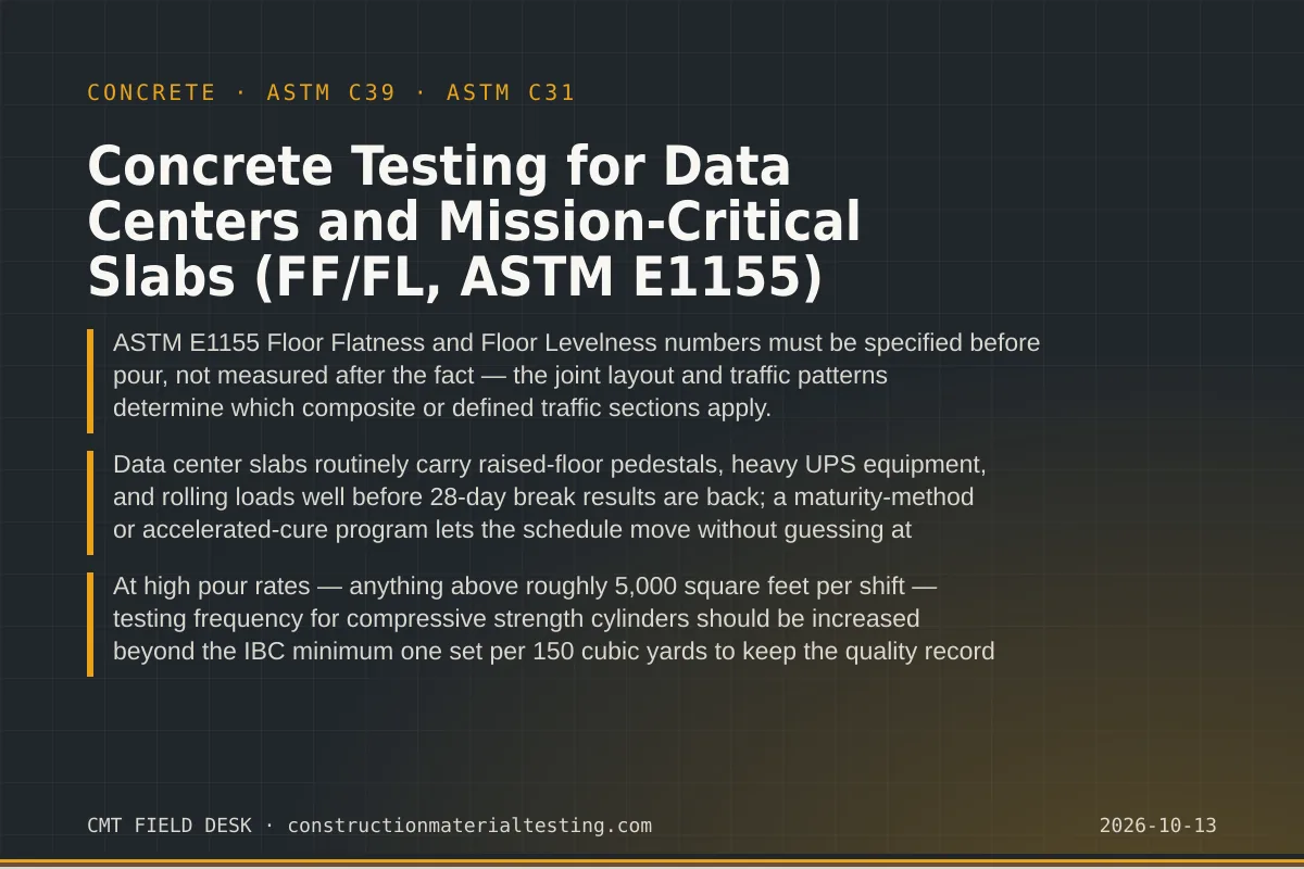
Why Data Center Concrete Testing Is Its Own Discipline
A warehouse slab and a data center slab may look identical at the concrete truck: same slump, same mix, same laser screed. The difference is what sits on top of them and how unforgiving those loads are. Raised-floor access systems — the bolted aluminum pedestals that support equipment tiles — transfer point loads directly through pedestals spaced on a fixed grid, typically 24 inches on center. A floor that is out of level by even a fraction of an inch causes pedestal shimming, which introduces differential deflection under rolling loads and, over time, micro-vibration that data center operators work hard to eliminate. Flatness tolerances that would be acceptable in a light-industrial tilt-up building are simply not tight enough here.
The testing program reflects that reality. Data center concrete testing is not just compressive strength cylinders and a slump cone — it is a coordinated effort that begins with the specification review, runs through pour night with in-process inspections, and continues with floor profile surveys and strength validation that support the critical path for raised-floor installation and equipment commissioning. Our technicians treat a data center slab the same way a structural engineer treats a post-tensioned transfer plate: nothing is assumed, everything is documented.
This guide covers the full arc: how ASTM E1155 flatness and levelness measurements work, how to structure the strength testing schedule so early loading decisions have data behind them, how joint layout interacts with profile numbers, and what to do when a pour goes sideways at 2 a.m. and the floor profiler reads a number the spec does not allow.
Understanding FF and FL: What the Numbers Actually Mean
Floor Flatness (FF) and Floor Levelness (FL) are statistical indices derived from elevation measurements taken on a defined grid. They are not pass/fail measurements in the conventional sense — they are population statistics. A higher number means a flatter or more level floor. FF describes short-range curvature: the change in slope over a 24-inch differential measurement. FL describes long-range tilt relative to a horizontal datum. A slab can have excellent flatness and terrible levelness, or vice versa, which is why both numbers must appear in the specification.
The FF number matters most for rolling wheel loads — the movement of server racks on casters, battery carts, and UPS units. A floor with low FF will cause equipment to rock on the pedestal grid and will accelerate wear on caster wheels and rack leveling feet. Most raised-floor manufacturers publish minimum FF requirements for their systems; those numbers should be incorporated directly into the slab spec rather than left to general contractor discretion. The FL number governs whether the floor plane itself is tilted relative to design — important for any equipment that uses gravity-fed cooling or leveling-sensitive instrumentation.
The standard that governs measurement procedure is ASTM E1155, and it is worth reading carefully before writing a specification. The standard defines how measurement sections are laid out, how many readings constitute a statistically valid sample, how to handle the area near joints and edges (which are excluded from composite F-numbers), and how to report results. The composite F-number for a floor is not simply the average of section F-numbers — it is calculated from the pooled population of differential readings across the entire measured area.
ASTM E1155 Measurement Procedure in Practice
Measurements under ASTM E1155 are taken with a floor profiler — a device that records elevations at fixed intervals as it traverses the slab in a defined pattern. The standard specifies measurement lines running in two perpendicular directions, with readings taken at 12-inch intervals. The profiler calculates the first differential (the change in elevation between adjacent readings) and the second differential (the change in slope) at every point. The FF index is derived from the second differentials; the FL index is derived from the first differentials referenced to a datum.
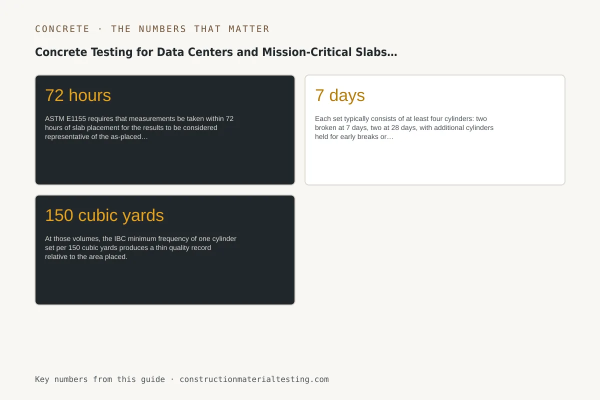
Timing is critical. ASTM E1155 requires that measurements be taken within 72 hours of slab placement for the results to be considered representative of the as-placed condition. After that window, drying shrinkage, creep under early loading, and temperature gradients can all shift the profile in ways that may not reflect the quality of the placement. On a data center project where a pour might happen on a Friday night and the floor profiler crew arrives Monday morning, a 72-hour deadline can be tighter than it looks. The inspection plan must include explicit hold points that protect that measurement window.
The standard distinguishes between defined-traffic floors and random-traffic floors. A raised-floor data center is effectively a defined-traffic floor: the equipment moves on fixed paths, the pedestals sit on a fixed grid, and the critical performance zone is everywhere rather than in one aisle. Some specifications are written as random-traffic composite F-numbers, which can mask poor performance in localized areas. We recommend working with the design team to specify minimum F-numbers for defined sections rather than relying solely on the composite number — a composite FF of 50 can still contain sections below 35 that will cause pedestal problems.
After the measurements are complete, the profiler software generates a report showing the composite FF and FL, the F-number for each measured section, a color-coded elevation map of the floor, and the locations of any readings that exceed the allowable differential. That report goes to the contractor, the EOR, and the owner's representative simultaneously, because any remediation decision — grinding, overlaying, or accepting the out-of-tolerance area — has structural and schedule implications.
Specifying FF/FL for Data Center Slabs: Typical Ranges and Table
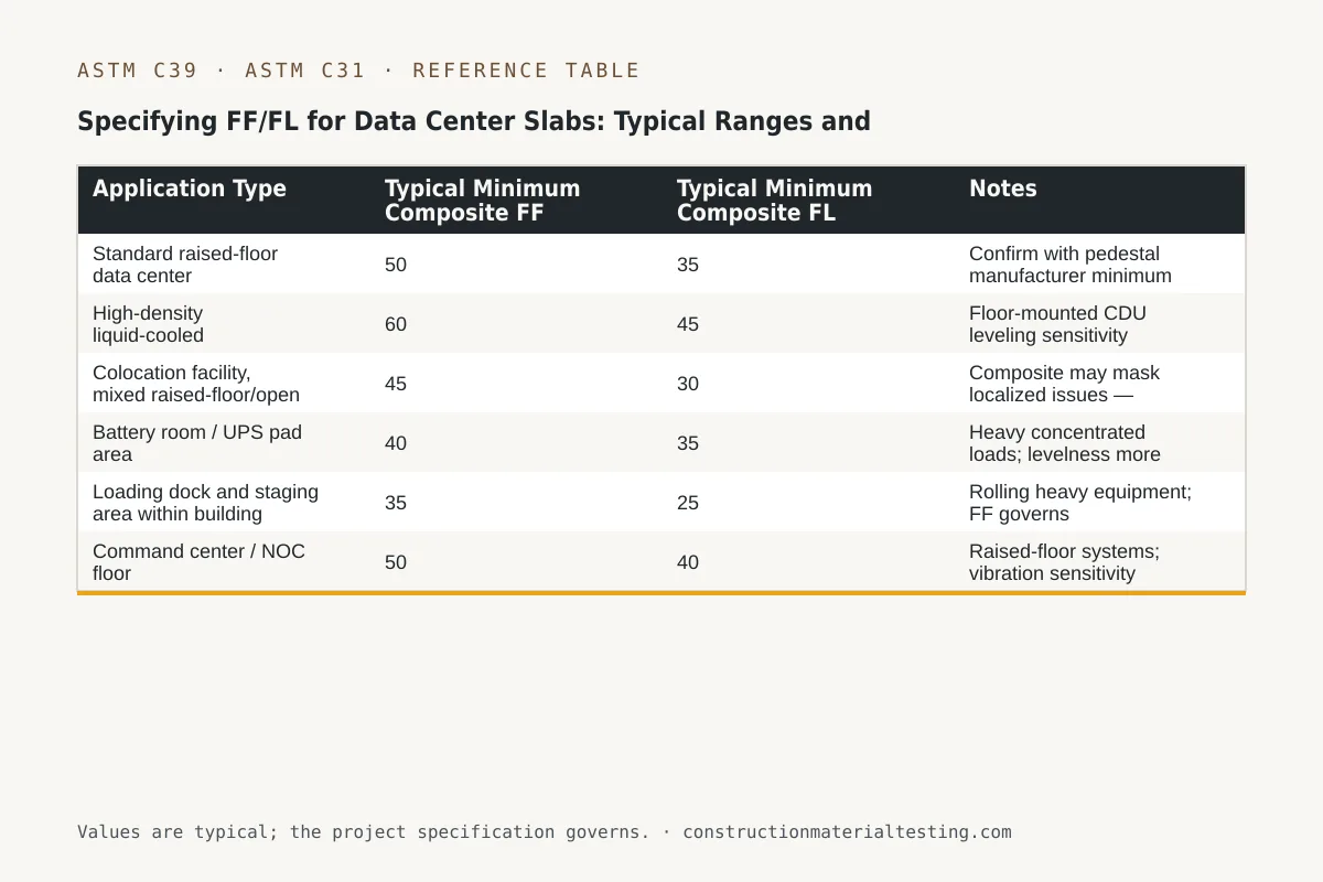
There is no single industry-wide required FF/FL for data center slabs because the tolerance is driven by the raised-floor system, the equipment weight, and the owner's operational requirements. That said, we see a consistent clustering of specifications in the field. A floor that will support a conventional raised-floor system with standard pedestals is typically specified at FF 50 / FL 35 minimum composite, with defined-section minimums several points lower. A floor supporting a high-density liquid-cooled rack environment — where the cooling distribution units are floor-mounted and the loads are concentrated — may push to FF 60 / FL 45 or higher.
The American Concrete Institute publishes guidance on floor flatness specifications through its ACI 117 tolerances standard and ACI 360 guide to slab-on-ground design. ACI 117 provides a framework for specifying and measuring F-numbers that aligns with ASTM E1155. Reading both documents together clarifies which tolerances govern during construction versus after final finishing, and how to handle areas near formed edges and construction joints that are excluded from the F-number calculation.
The table below summarizes the FF/FL ranges we commonly encounter on mission-critical projects, along with the corresponding application context. These are not code-mandated values — they are design decisions that must be confirmed with the project EOR and the raised-floor system manufacturer.
| Application Type | Typical Minimum Composite FF | Typical Minimum Composite FL | Notes |
|---|---|---|---|
| Standard raised-floor data center | 50 | 35 | Confirm with pedestal manufacturer minimum |
| High-density liquid-cooled environment | 60 | 45 | Floor-mounted CDU leveling sensitivity drives FL |
| Colocation facility, mixed raised-floor/open floor | 45 | 30 | Composite may mask localized issues — specify section minimums |
| Battery room / UPS pad area | 40 | 35 | Heavy concentrated loads; levelness more critical than flatness |
| Loading dock and staging area within building | 35 | 25 | Rolling heavy equipment; FF governs |
| Command center / NOC floor | 50 | 40 | Raised-floor systems; vibration sensitivity |
Joint Layout and Its Effect on F-Numbers
The single most common source of failed FF/FL readings on data center slabs is not the concrete mix or the finishing crew — it is a joint layout that was not coordinated with the screed pattern and the raised-floor grid. Construction joints, isolation joints, and saw-cut contraction joints all create elevation discontinuities that fall outside the ASTM E1155 measurement exclusion zone. The standard excludes a 2-foot border from walls, columns, and formed edges, and it excludes the readings immediately adjacent to joints — but everything within the panel is in play. A panel that is internally flat but curled at its edges because the saw cuts were late will still generate low FF readings near the joint.
Saw-cut timing is one of the most consequential decisions made during a data center pour. Cutting too early causes raveling and aggregate pullout; cutting too late allows random shrinkage cracks to form before the cuts relieve the tension. On a high-cementitious mix designed for early strength gain — which is common on data center slabs where the schedule demands early rack loading — the window between placement and the onset of shrinkage cracking can be narrow. Our field technicians monitor bleed water recession and surface temperature to help the contractor identify the optimal cut window, but that input needs to be requested before the pour, not the morning after.
Dowel baskets at construction joints must be positioned so they align with the raised-floor pedestal grid rather than crossing beneath pedestal locations. A dowel that prevents joint movement directly under a pedestal base plate will transfer differential deflection into the pedestal and eventually into the rack. This coordination between the structural engineer, the raised-floor installer, and the concrete contractor is rarely addressed in general conditions — it needs to be an explicit pre-pour RFI or submittal item. We have found it useful to overlay the dowel basket layout drawing on the raised-floor grid drawing before any concrete is placed.
Compressive Strength Schedule for Early Loading
Data center construction schedules are aggressive. The building shell goes up, the slab goes down, and before the concrete reaches its 28-day design strength, the mechanical and electrical contractors are rolling equipment across it, the raised-floor installer is setting pedestals, and the owner wants servers in racks. Managing that pressure without compromising structural integrity requires a strength testing program that provides real data at the decision points, not just a 28-day result that arrives after the fact.
The baseline requirement for compressive strength testing under IBC Section 1705.3 is one set of cylinders per 150 cubic yards of concrete placed, with a minimum of one set per day's pour. Each set typically consists of at least four cylinders: two broken at 7 days, two at 28 days, with additional cylinders held for early breaks or dispute resolution. For a data center slab where early loading is anticipated, we recommend adding cylinders designated for 3-day and 14-day breaks. The 3-day result — tested per ASTM C39 — gives the contractor an early indicator of mix performance and a basis for beginning light foot traffic and pedestal setting. The 14-day result, typically reaching 85–90 percent of design strength on most mix designs, is often the trigger for rolling rack loads.
Cylinder fabrication and curing per ASTM C31 is not optional on mission-critical work. Standard-cured cylinders — stored at 60–80°F in insulated curing boxes at the jobsite before transport to the lab — represent the concrete's strength potential under ideal conditions. Field-cured cylinders, left in representative locations on the slab, represent in-place strength and are a better basis for stripping or loading decisions. Both sets should be made on data center pours. The technician must protect cylinders from vibration, freezing, and solar heating during the first 24 hours; on an outdoor slab in Texas summer or a Phoenix jobsite, cylinder management in the first day is as important as the mix design itself.
The maturity method, described in ASTM C1074, offers a way to estimate in-place strength continuously without waiting for cylinder breaks. Temperature sensors embedded in the slab record a time-temperature history that is converted to a maturity index, which is then mapped to strength using a pre-established calibration curve for the specific mix. On fast-track data center projects, maturity monitoring has allowed contractors to make earlier, better-supported loading decisions than waiting for the next scheduled cylinder break. Implementing it correctly requires establishing the maturity-strength relationship before placement — which means it must be specified and procured in advance.
Testing Frequency at High Pour Rates
A mission-critical data center project with a deadline can see a single white-topping or ground-level slab poured at 10,000 to 20,000 square feet per shift, sometimes more if the contractor is running multiple laser screeds in sequence. At those volumes, the IBC minimum frequency of one cylinder set per 150 cubic yards produces a thin quality record relative to the area placed. We recommend that the inspection plan specify an additional trigger: one set per defined area — for example, every 5,000 square feet — whichever condition produces more frequent sampling.
High pour rates also increase the probability that a truckload of off-spec concrete gets placed before the field technician has test results in hand. Slump, air content, temperature, and unit weight should be measured on every fifth truck at minimum during high-rate pours, and the technician should have authority to reject a truck based on fresh concrete test results without waiting for the general contractor to make the call. That authority needs to be established in the project's special inspection agreement before the pour, not negotiated at the batch plant discharge point.
Our materials testing services are structured to support multi-technician deployments on large slab pours. When a pour rate demands continuous fresh concrete testing plus cylinder fabrication plus slab temperature monitoring plus real-time communication with the plant, one technician cannot do all of it without compromising the quality of any individual task. The inspection plan should identify the expected pour rate, estimate the truck frequency, and staff accordingly. For projects in our regional dispatch areas — including Dallas-Fort Worth, Phoenix, and Atlanta — we coordinate technician staffing as part of the pre-construction meeting.
What Happens When FF/FL Results Fall Below Specification
A floor profiler report that shows out-of-tolerance sections is not automatically a rejection. ASTM E1155 produces data; the specification determines consequences. The first step when results come in low is to confirm that the measurement was conducted correctly — that the profiler was calibrated, that the measurement lines were laid out per the standard, and that any areas near joints or edges were properly excluded. A measurement error that inflates the number of out-of-tolerance readings is worth catching before remediation discussions begin.
If the measurement is confirmed accurate and sections are below the specified minimum, the options are grinding, overlay, or accept-in-place with engineering justification. Diamond grinding is effective for improving FF numbers — it removes high spots and brings the local second differentials into tolerance. It does not improve FL numbers, because FL is about overall tilt rather than local bumps. An overlay can improve both, but it adds dead load to the slab, raises the finished floor elevation, and must be specified with appropriate bonding and thickness requirements. Accept-in-place requires the EOR to evaluate whether the as-built condition satisfies structural performance requirements and whether the raised-floor manufacturer can accommodate the deviation — which usually means the pedestal shimming envelope needs to be checked.
The worst outcome is a floor that is accepted in the field without documentation and later causes pedestal problems that are attributed to the raised-floor installer or the equipment vendor. We always recommend that any formal deviation from the specified FF/FL be recorded in a non-conformance report, reviewed by the EOR, and closed with a written disposition before the raised-floor installation begins. That paper trail protects all parties when a problem surfaces during commissioning.
Coordinating the Full Quality Record
A data center slab generates a substantial documentation package: fresh concrete field records for every tested load, cylinder fabrication logs, curing records, lab break reports at multiple ages, floor profile reports with section-by-section F-numbers, saw-cut timing logs, and any non-conformance reports. All of that documentation needs to flow to the same place in real time, not be assembled from four different contractors' email threads six months after substantial completion.
The special inspection program under IBC Section 1705.3 requires that inspection reports be furnished to the building official, the engineer of record, and the owner. Many data center owners — particularly those operating under a colocation model where the facility itself must be certified by third-party auditors — have additional documentation requirements beyond the code minimum. Those requirements should be identified in the owner's project requirements (OPR) document and incorporated into the inspection agreement before any work begins.
Temperature differentials during curing deserve specific attention on data center slabs. ACI 305 guidance on hot weather concreting and ACI 306 guidance on cold weather concreting both apply depending on season and geography, and temperature differentials between the slab surface and interior of more than 35°F during the first 24 hours can cause surface cracking that affects both F-numbers and long-term durability. Monitoring slab temperature at the surface, mid-depth, and ambient during the curing period and recording those readings in the quality documentation gives the project team the information needed to defend the curing program if questions arise later.
Where Data Center Concrete Testing Fits on Your Project
The floor is usually one of the earliest permanent elements to be placed, and it is one of the elements that is hardest to correct after the raised floor goes in and the racks are commissioned. Getting the testing and inspection program right before the first pour — not after — is what separates a data center project that commissions on schedule from one that loses weeks to grinding crews and engineering reviews.
We work with general contractors, construction managers, and owner's representatives from pre-construction through the final floor profile survey. If you are in the planning or bid phase for a mission-critical slab project, request a proposal and we will review your specification, identify the testing triggers that matter for your schedule, and staff the pour appropriately from our network of regional dispatch hubs.
Get our guides in your Google results
Add Construction Materials Testing as a preferred source and Google shows our guides more often when you search for testing topics.