

Why Pavement Specs Call for Beam Tests Instead of Cylinders
Pavement concrete fails in bending, not compression. A loaded slab bends under wheel loads until the tension face cracks, and that crack propagates upward. Cylinder breaks measure resistance to axial compression, which is a fundamentally different stress state. Because flexural strength test concrete results directly characterize the failure mode that governs pavement design, both highway agencies and airport engineers specify modulus of rupture (MR) as the acceptance criterion rather than—or in addition to—compressive strength.
Rigid pavement thickness is calculated from MR using mechanistic design methods. If the actual MR is lower than the design value, the slab is effectively thinner than the engineer intended, and fatigue life drops sharply. This is why TxDOT pavement items and FAA-governed airfield paving require beam specimens to be cast from the same concrete that goes into the slab, tested at the same age, and evaluated against a minimum MR before the work is accepted. Our ASTM C78 flexural strength testing service supports that acceptance process from field casting through laboratory reporting.
Cylinders are still cast on pavement jobs—primarily to track early strength gain for form-strip and opening-to-traffic decisions—but they do not substitute for beams when the specification language calls for MR. Engineers should confirm which result controls their pay item before mobilizing; we see projects where both are required and others where only one is.
Beam Molding in the Field: Dimensions, Consolidation, and Initial Curing
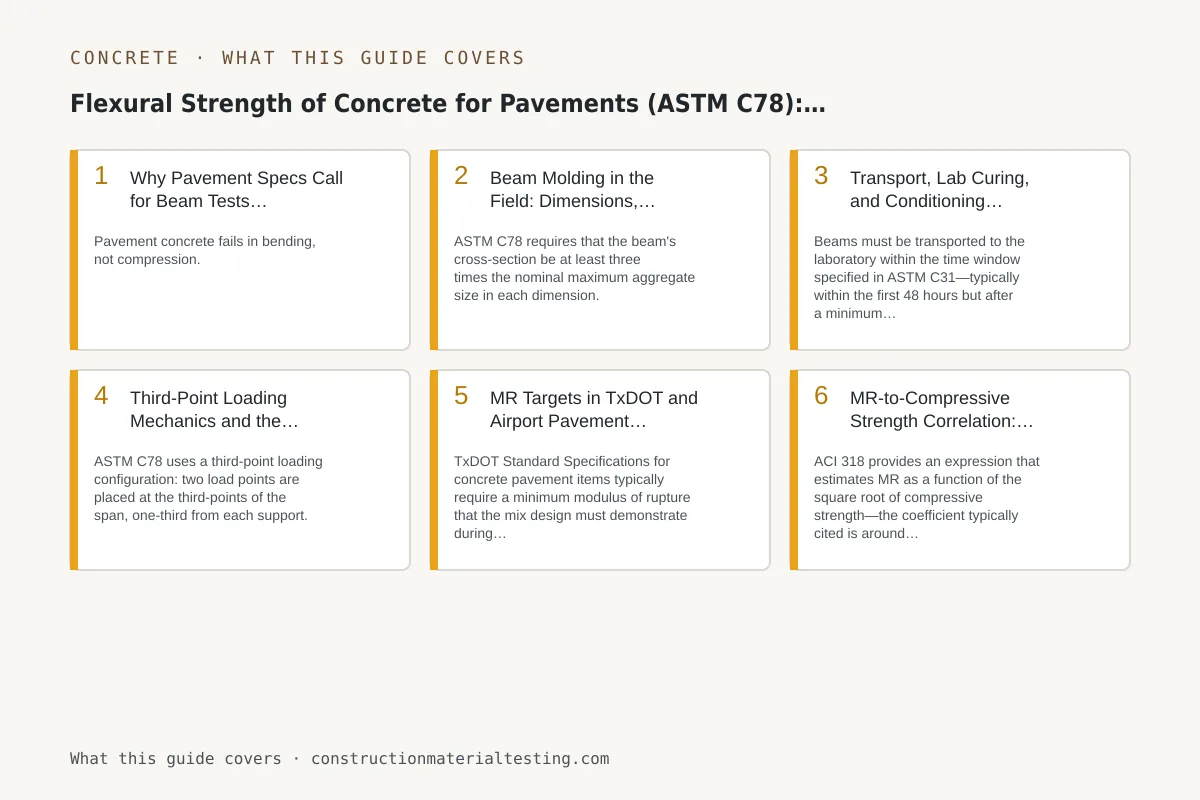
ASTM C78 requires that the beam's cross-section be at least three times the nominal maximum aggregate size in each dimension. For the 1½-inch aggregate common in pavement mixes, that means a minimum 6 × 6-inch cross-section. The standard test span is 18 inches, which requires a beam at least 20 inches long to seat properly on the load frame; most labs and agencies specify 6 × 6 × 21-inch molds to provide handling clearance. Using a shorter or narrower mold—sometimes done in the field when standard molds are unavailable—produces results that cannot be reported to the standard and should be rejected outright.
Fill the mold in two layers, rodding or vibrating each layer fully. For slumps under 3 inches, internal vibration is appropriate; for higher slumps, rodding is typically used. Strike off the top flush with the mold edge and finish lightly—do not float the surface excessively, as that can draw paste to the top and create a non-representative tension face. Mark each beam clearly with a waterproof marker or tag, recording the sample location, time of casting, and batch ticket number. Beams are heavier than cylinders and more fragile in the green state, so set them on a flat, vibration-free surface immediately.
Initial curing is the step most often shortcut on pavement jobs. ASTM C31, which governs initial curing for acceptance specimens, requires maintaining the concrete between 60°F and 80°F for the first 24 hours. In Texas summers, ambient air at a slab location can easily run 95°F or above; leaving an unprotected beam in direct sun on a black paving mat will accelerate hydration, can introduce thermal cracking, and will almost certainly produce a low break. Cover beams with wet burlap and insulating blankets, and monitor temperature. Detailed guidance on that process lives in our ASTM C31 field curing reference.
Transport, Lab Curing, and Conditioning Before the Flexural Strength Test
Beams must be transported to the laboratory within the time window specified in ASTM C31—typically within the first 48 hours but after a minimum initial curing period. Use a padded vehicle or foam-lined transport crate. A beam that shifts or bounces during transport can develop microcracking that depresses the MR result; this is especially true for beams tested at early ages. We pad beams individually and use low-speed routes when practical.
Once in the lab, beams are moist-cured in a lime-saturated water bath or a mist room held at 73 ± 3°F until the test age. The conditioning step immediately before testing is critical and often misunderstood: ASTM C78 requires that beams be tested in a surface-dry but internally moist condition, not oven-dried and not soaking wet with free water on the surface. We remove beams from the curing tank, blot the surface, and test within the time limit specified in the standard—typically no more than a few minutes out of water—because drying begins immediately and measurably lowers MR.
Measure the beam cross-section at three points along the middle third of the span and average them. Record width and depth separately; these values go directly into the MR calculation and small errors compound. The span length used in the calculation is the actual distance between support contact lines, not the mold length.
Third-Point Loading Mechanics and the Flexural Strength Test Calculation
ASTM C78 uses a third-point loading configuration: two load points are placed at the third-points of the span, one-third from each support. This creates a constant bending moment across the middle third of the beam with zero shear in that zone. The practical effect is that the specimen fails at its weakest cross-section in pure flexure, rather than directly under a load point where shear and flexure interact. That distinction matters because it removes a variable and makes the result a true material property.
Load is applied at a continuous rate such that stress increases at 125 to 175 psi per minute. Modern servo-hydraulic frames apply load in displacement control, and the technician must set the rate correctly based on the estimated break load and beam geometry—rushing the load rate artificially inflates the result; loading too slowly can allow creep effects. We watch the load-displacement curve in real time; a flat or dropping curve before audible cracking usually signals a seating problem at a support, not a material issue.
The modulus of rupture is calculated from the break load and the failure location. When the fracture falls within the middle third of the span, the standard formula applies: MR = PL / (bd²), where P is the maximum load, L is the span, b is the average width, and d is the average depth. When the fracture falls outside the middle third by more than 5 percent of the span length, the result is discarded under ASTM C78. We mark the span thirds on every beam with a grease pencil before seating it so the fracture location can be documented immediately and unambiguously.
MR Targets in TxDOT and Airport Pavement Specifications
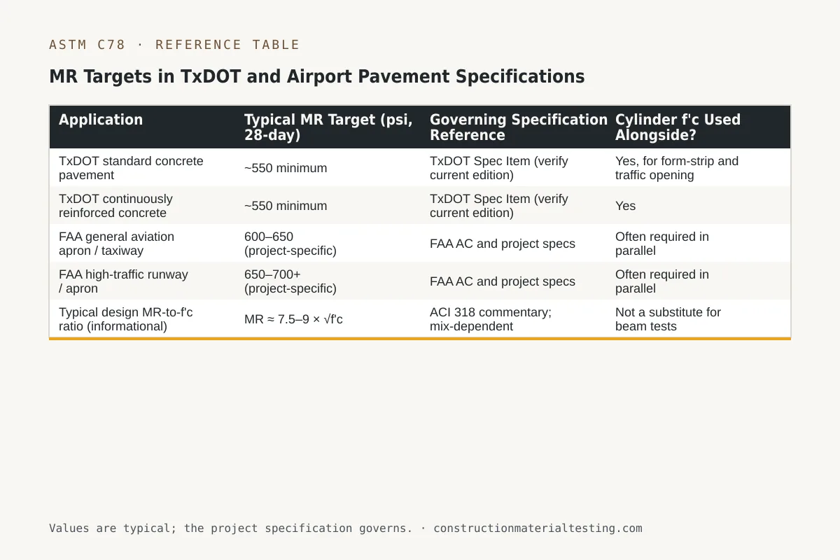
TxDOT Standard Specifications for concrete pavement items typically require a minimum modulus of rupture that the mix design must demonstrate during trial batch work and that field specimens must meet for lot acceptance. Historically those targets have centered near 550 psi at 28 days for standard highway pavement concrete, though the exact requirement varies by specification item and any project-specific special provisions. Engineers should read the current spec item and any addenda rather than relying on memory of a prior project's number.
Airport pavement work governed by FAA advisory circulars and project-specific geotechnical and structural reports often targets higher MR values—600 to 700 psi or above is not unusual for high-traffic apron and runway slabs—because aircraft gear loads and departure angles create demanding bending conditions. The structural design of the rigid pavement back-calculates the required MR from a target number of equivalent single-wheel load repetitions; if the field concrete underperforms that design MR even modestly, the fatigue life shortfall is disproportionately large. Our materials testing services for pavement projects include trial batch evaluation and production monitoring to catch mix performance issues before they become acceptance failures.
Many pavement specifications also permit the engineer to establish a correlation between MR and compressive strength for quality-control purposes only—allowing cylinder breaks to serve as a leading indicator between beam test ages. That correlation must be project-specific and mix-specific; a generic ratio applied from a different mix or aggregate source is unreliable. We establish correlations by running both beams and cylinders from the same batches across multiple ages and fitting a project-specific regression. More on cylinder testing fundamentals is at our ASTM C39 compressive strength reference.
| Application | Typical MR Target (psi, 28-day) | Governing Specification Reference | Cylinder f'c Used Alongside? |
|---|---|---|---|
| TxDOT standard concrete pavement | ~550 minimum | TxDOT Spec Item (verify current edition) | Yes, for form-strip and traffic opening |
| TxDOT continuously reinforced concrete pavement | ~550 minimum | TxDOT Spec Item (verify current edition) | Yes |
| FAA general aviation apron / taxiway | 600–650 (project-specific) | FAA AC and project specs | Often required in parallel |
| FAA high-traffic runway / apron | 650–700+ (project-specific) | FAA AC and project specs | Often required in parallel |
| Typical design MR-to-f'c ratio (informational) | MR ≈ 7.5–9 × √f'c | ACI 318 commentary; mix-dependent | Not a substitute for beam tests |
MR-to-Compressive Strength Correlation: What It Can and Cannot Do
ACI 318 provides an expression that estimates MR as a function of the square root of compressive strength—the coefficient typically cited is around 7.5 for normal-weight concrete, though ACI 318 presents it in the context of structural design calculations rather than as a field acceptance tool. In practice, the ratio between MR and √f'c varies meaningfully with aggregate type, aggregate angularity, paste volume, and water-cementite materials ratio. A crushed limestone mix and a rounded river gravel mix at the same design compressive strength can produce noticeably different MR values.
We use the correlation as a flag, not a decision. If cylinders from a batch break significantly below the trend line established during trial batch work, we hold the beam results for that lot with extra scrutiny and may recommend additional field cores or additional beam sets depending on the specification's remedy provisions. If cylinders are on trend and beams come back low, we look first at curing and transport conditions before attributing the result to the concrete itself. Our ASTM C31 specimen handling procedures are designed specifically to eliminate handling variables so that a low result means something about the material rather than something about how the specimen was treated.
One situation where the correlation genuinely helps is traffic-opening decisions. Pavement can typically open to construction equipment or limited traffic once MR reaches a threshold percentage of the design MR—often 75 percent. Because beams from earlier ages may already be in the lab breaking under the standard protocol, a well-established correlation lets the engineer use intermediate cylinder breaks to estimate whether the slab is approaching that threshold without having to cast additional early-age beams solely for that purpose.
Where Beam Testing Fits on Your Project
Flexural strength testing is not a formality on pavement work—it is the direct measurement of the property that governs slab thickness and fatigue life. Getting the process right from mold selection through lab conditioning and load-frame procedure determines whether the data you submit to the agency actually reflects the concrete in the pavement. When testing is done carelessly, low results that have nothing to do with the concrete trigger costly investigation, coring programs, or rejection disputes.
We provide ASTM C78 beam casting, transport, curing, and testing as part of our concrete pavement inspection programs, with dispatch from our Sugar Land laboratory and regional hubs across Texas. If your project involves TxDOT concrete pavement items, airport paving, or any other spec that requires modulus of rupture acceptance, request a proposal early so we can coordinate technician scheduling with your paving operations and confirm the testing frequency required by your specification.
Get our guides in your Google results
Add Construction Materials Testing as a preferred source and Google shows our guides more often when you search for testing topics.