
Why Concrete Test Cylinders Are Made in the First Place
Every structural concrete placement carries an implicit question: did this mix actually develop the compressive strength the engineer specified? The cylinder is the evidence. Under ASTM C31, technicians cast companion specimens from the same load of concrete that goes into the structure, cure them under controlled conditions, and then break them in compression at specified ages—most commonly 7 and 28 days, though 3-day and 56-day breaks appear on certain project specifications.
The result is a number in psi or MPa that the engineer of record compares against the specified design strength, f'c. If the 28-day average of two cylinders from the same sample falls below f'c, or if any single cylinder falls more than a code-defined margin below f'c, the engineer must investigate. The ACI 318 Building Code sets the acceptance criteria; the cylinders themselves are how the data is generated. A cylinder that was cast, cured, or transported incorrectly does not tell you the strength of the concrete—it tells you the strength of a compromised specimen, and those two numbers can differ by more than you want to explain to a project owner.
Our concrete and materials testing services involve casting cylinders on projects ranging from tilt-up slabs to post-tensioned elevated decks, and the field steps described below are the same regardless of project type. The procedure looks simple. Done carelessly, it produces data nobody can use.
Sampling Concrete Before You Fill a Mold
Casting starts with a representative sample, and ASTM C31 is specific about where in the discharge that sample comes from. You do not pull concrete from the first or last portion of a truck's discharge. The sample is composite—meaning you collect it from at least two increments taken at regular intervals during the middle portion of the load. The combined sample must be large enough to run all the fresh concrete tests (slump, air, unit weight, temperature) and still fill the required number of cylinders without resampling.
Location matters too. The sample must be taken at the point of discharge into the structure, or as close to placement as practicable. Sampling from the truck chute before concrete has traveled through a pump or a long tremie can give you a different mix than what is actually going into the slab. When a pump is used, ASTM C31 directs sampling after the pump—not before it. We see this step skipped often enough that it is worth stating plainly: sampling at the wrong point can give you a passing result on a failing mix, or a failing result on concrete that actually placed at the right consistency.
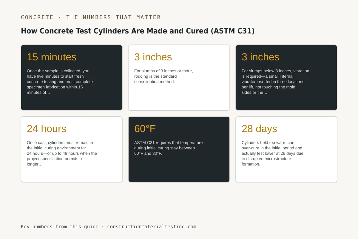
Once the sample is collected, you have five minutes to start fresh concrete testing and must complete specimen fabrication within 15 minutes of sampling. That clock is tighter than many contractors expect, especially on a busy deck pour with equipment moving around you.
Filling and Rodding: How Concrete Test Cylinders Are Actually Cast
The standard cylinder for structural concrete in the United States is 4 inches in diameter by 8 inches tall, though 6×12 cylinders are still specified on some heavy civil and pavement projects. ASTM C31 requires single-use plastic molds that meet dimensional tolerances; reusing molds is not permitted. Before filling, the mold interior should be lightly oiled so the hardened cylinder releases cleanly at the laboratory.
For slumps of 3 inches or more, rodding is the standard consolidation method. The mold is filled in two equal layers for a 4×8, and each layer receives 25 strokes of a 3/8-inch diameter rod distributed uniformly across the cross section. The rod penetrates the previous layer by about an inch to ensure bonding between lifts. After rodding each layer, tap the outside of the mold 10 to 15 times with a mallet to close any voids the rod created. For slumps below 3 inches, vibration is required—a small internal vibrator inserted in three locations per lift, not touching the mold sides or the previous layer.
After the final layer is consolidated, strike off the top surface with a flat bar or trowel so it is level with the top of the mold. The surface does not need to be polished smooth, but it should not be concave or convex by more than 1/8 inch. A grossly uneven top creates a stress concentration when the cylinder is capped and compressed, and the break will reflect that artifact rather than the concrete's actual strength. Apply the lid or plastic cap supplied with the mold immediately after finishing to reduce evaporation.
Initial Curing: The 60–80°F Window That Makes or Breaks the Test
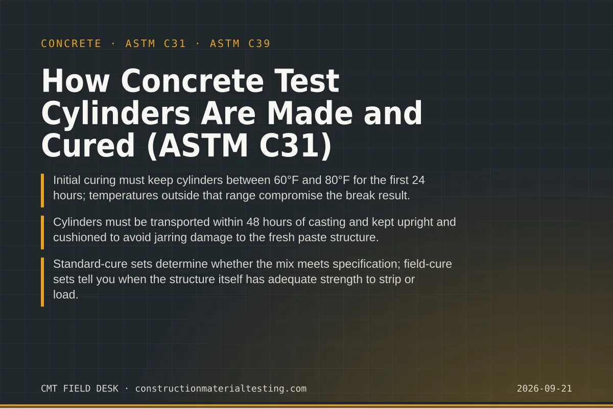
Once cast, cylinders must remain in the initial curing environment for 24 hours—or up to 48 hours when the project specification permits a longer window. ASTM C31 requires that temperature during initial curing stay between 60°F and 80°F. That range is not conservative guidance; it reflects the temperature sensitivity of early cement hydration. Cylinders held too cold hydrate slowly and may record artificially low early strength. Cylinders held too warm can over-cure in the initial period and actually test lower at 28 days due to disrupted microstructure formation.
This is where the windowsill problem lives. A cylinder set on a sun-exposed windowsill in a site trailer can see temperatures well above 80°F within an hour of casting, especially in Texas summers. A cylinder left in an unheated structure overnight in January can drop below 60°F before morning. Neither specimen will produce a valid result, and neither failure is recoverable. The cylinder cannot be recured once the 24-hour window has passed.
The practical solution is an insulated curing box with a thermometer—essentially a foam cooler with a small heat source or ice packs sized to hold the temperature band. We place a calibrated thermometer inside and log the temperature at the beginning and end of the initial curing period. If the log shows the temperature went out of range, that information goes in the field report. Some specifications require continuous temperature logging for initial cure; we use electronic dataloggers on those projects. The cylinders must also stay undisturbed during initial curing—no moving them to clear the trailer floor, no stacking objects on top.
Transport Window and Standard vs. Field-Cure Sets
After initial curing is complete, standard-cure cylinders must be transported to the laboratory and placed in the moist-curing room within the time frame ASTM C31 specifies—generally within 48 hours of casting. During transport, cylinders must be kept upright and protected from vibration and impact. A cylinder that gets tipped on its side in the back of a pickup, or bounced over a rough road without cushioning, can develop internal microcracking that reduces the break result by more than the test's inherent variability. We transport cylinders in padded carriers that hold them vertical and isolate them from road shock.
Standard-cure sets and field-cure sets serve entirely different purposes, and confusing them is a significant error. Standard-cure cylinders are immediately transferred to laboratory moist-room conditions—73.4°F ± 3°F and at least 95 percent relative humidity—after transport. Those breaks determine whether the concrete mix satisfied the specified design strength. They are the acceptance specimens under ACI 318.
Field-cure cylinders, by contrast, stay on the job site and experience whatever temperature and moisture conditions the structure itself experiences. They are cured alongside the pour, or as close to it as practicable, covered with the same insulating blankets or curing compound used on the slab. Their breaks estimate in-place strength—used to decide when it is safe to strip formwork, apply post-tensioning, or allow traffic. Field-cure breaks are not substitutes for standard-cure breaks for mix acceptance, and using them that way is a common misunderstanding that can expose a project to liability.
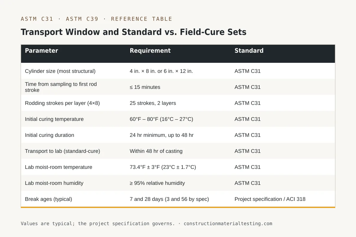
The table below summarizes the key procedural parameters from ASTM C31 in one place.
| Parameter | Requirement | Standard |
|---|---|---|
| Cylinder size (most structural) | 4 in. × 8 in. or 6 in. × 12 in. | ASTM C31 |
| Time from sampling to first rod stroke | ≤ 15 minutes | ASTM C31 |
| Rodding strokes per layer (4×8) | 25 strokes, 2 layers | ASTM C31 |
| Initial curing temperature | 60°F – 80°F (16°C – 27°C) | ASTM C31 |
| Initial curing duration | 24 hr minimum, up to 48 hr | ASTM C31 |
| Transport to lab (standard-cure) | Within 48 hr of casting | ASTM C31 |
| Lab moist-room temperature | 73.4°F ± 3°F (23°C ± 1.7°C) | ASTM C31 |
| Lab moist-room humidity | ≥ 95% relative humidity | ASTM C31 |
| Break ages (typical) | 7 and 28 days (3 and 56 by spec) | Project specification / ACI 318 |
| End preparation (cap or pad) | Must comply with ASTM C617 or C1231 | ASTM C39 |
Laboratory Moist Room and End Preparation Before the Break
Once cylinders arrive at the laboratory, they are logged in, labeled with the sample data from the field report, and placed in the moist room. The moist room is not optional equipment—it is a controlled environment that ASTM C31 specifies by temperature and humidity, and our laboratory maintains continuous records of both. Cylinders sit on racks, not stacked, with space for air circulation on all sides. They stay in the moist room until the day of the break, when they are pulled and tested within the tolerance ASTM C39 specifies for the break age—a 28-day break, for example, must be run between 27 and 29 days after casting.
Before compression testing, the cylinder ends must be prepared so they are flat, parallel to each other, and perpendicular to the cylinder axis. Two methods are in common use. Sulfur mortar capping, covered by ASTM C617, involves pouring a molten cap onto each end; it works well but requires handling of hot material and a cure time before testing. Neoprene pad end preparation, covered by ASTM C1231, uses steel retaining rings with neoprene inserts of a specified durometer. Pads must match the cylinder diameter exactly—a 4-inch pad on a 6-inch cylinder is a calibration failure. ASTM C1231 limits the reuse of neoprene pads based on their hardness after use; we track pad condition as part of the laboratory quality system.
The actual compression test follows ASTM C39. The technician centers the cylinder under the spherically seated bearing block, applies load at a controlled rate between 35 and 70 psi per second, and records the maximum load at failure. The result is reported in psi along with the fracture pattern, which is classified on a standard diagram. A cone-and-shear fracture is typical and expected; a columnar or diagonal fracture may indicate end-preparation problems, and that observation belongs in the report.
Where This Fits on Your Project
Concrete test cylinders are a contractual deliverable on virtually every permitted concrete structure, and the data they produce follows the project into the permanent record. Special inspection requirements under IBC Section 1705 routinely include cylinder fabrication and reporting as part of the concrete inspection program. Getting the procedure right—sampling location, initial curing temperature, transport timing, cure set type—is not a detail that can be addressed after the fact. A cylinder broken with a compromised chain of custody is a data point nobody can defend.
If you are coordinating a concrete placement and want to confirm the inspection program covers fabrication and curing correctly, or if you need field-cure and standard-cure sets on the same pour, our team can walk through the requirement with you before the concrete truck arrives. Visit our ASTM C31 test method page for a specification-level overview, or request a proposal to discuss how cylinder testing fits into your project's inspection scope.
Get our guides in your Google results
Add Construction Materials Testing as a preferred source and Google shows our guides more often when you search for testing topics.