
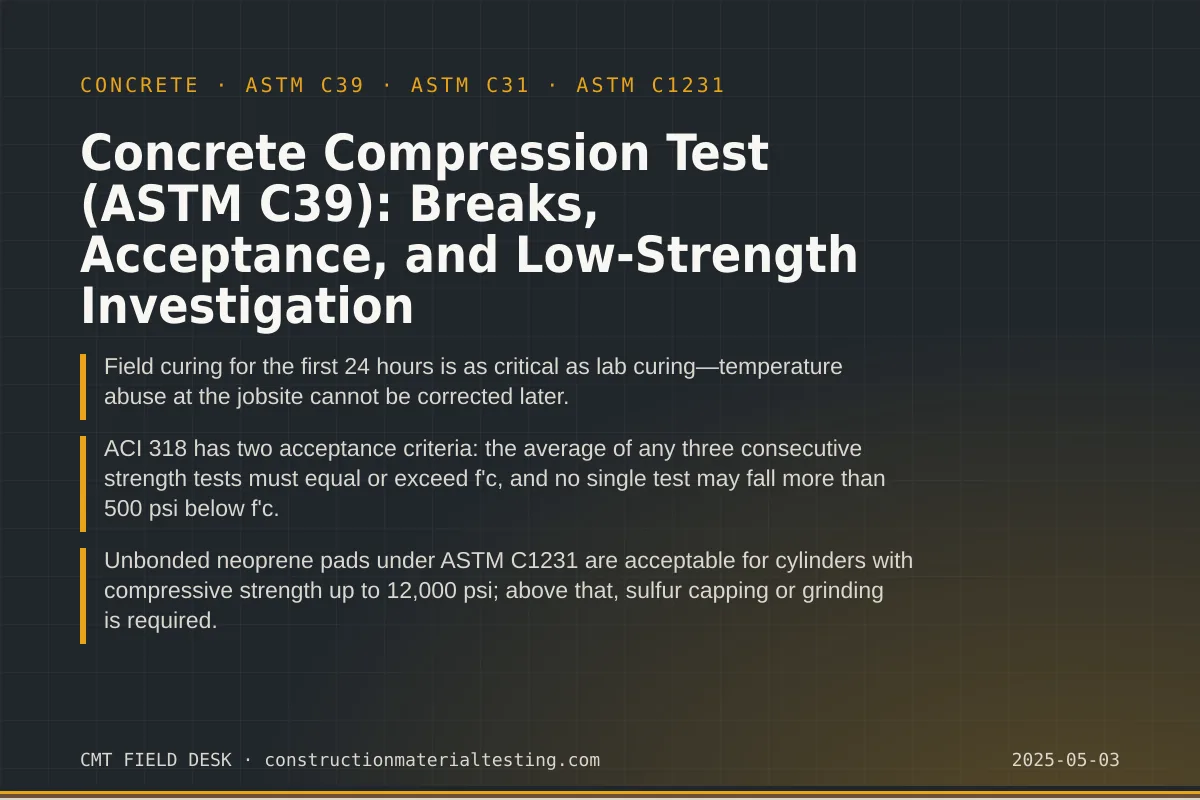
Why the Concrete Compression Test Is the Backbone of Structural QA
Every structural concrete placement on a project—slabs, columns, walls, foundations—carries a specified compressive strength, written as f'c on the drawings. The concrete compression test under ASTM C39 is the primary instrument engineers and inspectors use to confirm that the placed concrete will actually develop that strength. Nothing in the field is more consequential: a missed strength requirement can delay a floor pour, trigger a stop-work order, or in the worst case require removal and replacement of hardened concrete worth far more than the cost of the test.
What makes ASTM C39 powerful is its precision. The standard prescribes cylinder dimensions, curing environment, end preparation, machine calibration, loading rate, and even how to classify the fracture pattern after the break. When every variable is controlled, the number that comes out of the machine reflects the concrete's strength—not the technician's technique or the condition of the equipment. When those variables are not controlled, the number is noise. That distinction is why special inspection programs require that cylinder making, curing, and testing be performed by trained, ACI-certified technicians following documented procedures.
This guide covers the full sequence: field cylinder fabrication under ASTM C31, standard and initial curing, end preparation options, the test itself, fracture pattern interpretation, ACI 318 acceptance criteria, and the investigation path when results come back low. We also address the practical edge cases—cylinders left in the sun on a flatbed, caps that slip, machines out of calibration—because those are exactly the situations where a field technician needs a clear framework for what to do next.
Making and Curing Cylinders in the Field (ASTM C31)
A compressive strength result is only as valid as the cylinder that produced it. ASTM C31 governs field fabrication and curing of test specimens; following it is not optional if you want a number that represents the concrete in the structure. The standard 6×12 inch cylinder (150 mm × 300 mm) is the traditional test specimen, but 4×8 inch cylinders (100 mm × 200 mm) are increasingly common on projects using higher-strength mixes or where concrete volume is limited. ACI 318 and most project specifications accept either size, provided the cylinder diameter is at least three times the nominal maximum aggregate size.
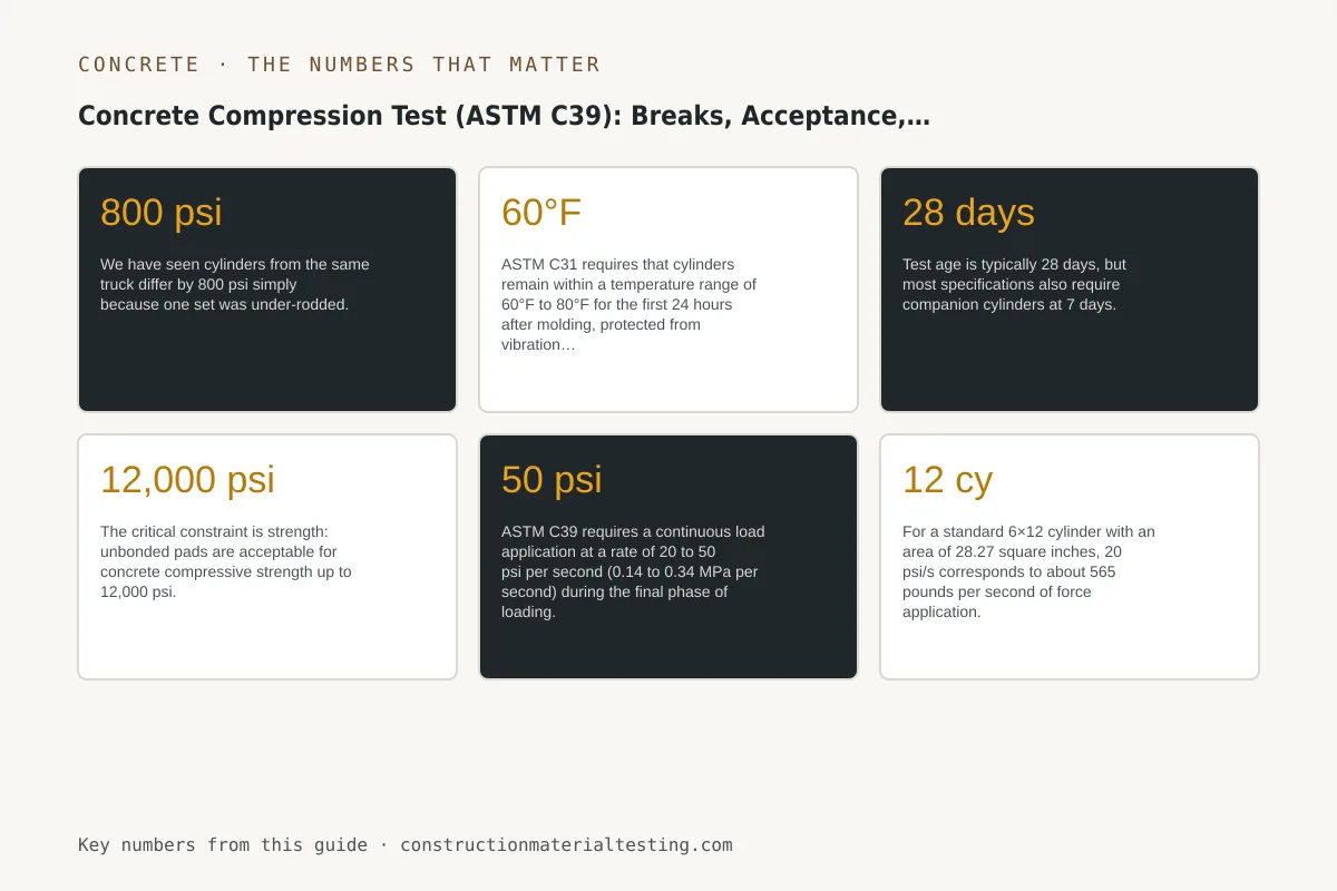
Consolidation method depends on slump. For concrete with slump greater than one inch, rodding is the standard approach—25 strokes per layer for a 6×12 mold, 25 strokes for each of two layers in a 4×8 mold. Below one inch of slump, internal vibration is required. Incomplete consolidation leaves air voids that reduce measured strength, sometimes dramatically. We have seen cylinders from the same truck differ by 800 psi simply because one set was under-rodded.
Initial curing is where field control breaks down most often. ASTM C31 requires that cylinders remain within a temperature range of 60°F to 80°F for the first 24 hours after molding, protected from vibration and damage. On summer jobs in the Houston area that means cylinders stored in direct sun on a flatbed truck or on a concrete slab baking in the afternoon heat will be heat-cured at temperatures that accelerate early hydration and reduce long-term strength. We use insulated curing boxes with thermometers when ambient conditions are marginal. After initial curing, cylinders must be transported to the laboratory without jarring or freezing, then placed in a moist curing room or lime-water tank maintained at 73°F ± 3°F until test day. Detailed field procedures are documented in our ASTM C31 test method page.
Test age is typically 28 days, but most specifications also require companion cylinders at 7 days. The 7-day break gives an early indicator—roughly 65 to 75 percent of 28-day strength for ordinary portland cement mixes—without providing a compliance result. Additional companion cylinders are sometimes cast for 56-day or 90-day testing when SCM-heavy mixes (slag, fly ash) are specified, because those mixes continue gaining strength well beyond 28 days. The project specification controls which ages are required and how many cylinders per set.
End Preparation: Capping Versus Unbonded Pads
ASTM C39 requires that the two bearing ends of a cylinder be essentially plane and perpendicular to the cylinder axis before testing. If the ends are not flat, load concentrates on high spots rather than distributing uniformly across the cross section, and the measured strength drops. End preparation is accomplished by one of three methods: sulfur mortar capping, grinding, or unbonded neoprene pads under ASTM C1231.
Sulfur capping has been the traditional approach for decades. A molten sulfur-mortar compound is poured into a steel capping plate and the cylinder end is pressed into it, producing a thin, hard cap that cures in minutes. The cap transfers load uniformly and adds negligible thickness. The limitation is the fume hazard from the melting sulfur and the time involved when processing large cylinder sets.
Unbonded caps—neoprene pads confined in steel retainer rings—have become the practical standard in most laboratory settings because they are faster, produce no fumes, and are reusable. ASTM C1231 governs their use. The critical constraint is strength: unbonded pads are acceptable for concrete compressive strength up to 12,000 psi. Above that threshold, the pad deforms enough under load to affect the result, and sulfur caps or ground ends are required. Pad durometer and pad thickness are also specified; worn or out-of-spec pads must be replaced. We track pad usage and inspect them before each test set.
Grinding is the third option. A surface grinder removes enough material to achieve the required planeness tolerance—ASTM C39 allows a maximum deviation of 0.002 inch from a plane. Grinding is slow but produces the most geometrically perfect end, which is why it is preferred for research work and for very high-strength cylinders where pad compliance is a concern.
Running the Concrete Compression Test: Loading Rate and Procedure
The testing machine must be calibrated and verified to meet ASTM E4 requirements before any cylinders are tested. Our machines are checked on a schedule consistent with our quality system requirements, and the calibration record travels with the test data. The machine must be capable of applying load at the rate ASTM C39 specifies and of measuring the applied force within one percent accuracy.
Loading rate is one of the most consequential variables in the test and one of the easiest to get wrong. ASTM C39 requires a continuous load application at a rate of 20 to 50 psi per second (0.14 to 0.34 MPa per second) during the final phase of loading. For a standard 6×12 cylinder with an area of 28.27 square inches, 20 psi/s corresponds to about 565 pounds per second of force application. Going faster than 50 psi/s tends to report higher strength than the concrete actually has; going slower than 20 psi/s can produce lower readings. Modern servo-controlled machines make rate compliance straightforward, but older displacement-controlled machines require the technician to monitor and adjust the hand control actively.
The technician places the cylinder on the lower bearing block, seats the upper spherically seated block against the cylinder end with hand pressure, and begins loading. Once load exceeds roughly half the expected failure load, the spherical seat should lock in place and should not be adjusted. The machine continues loading until the cylinder fails. Maximum load is recorded. Compressive strength is calculated as the maximum load divided by the average cross-sectional area of the cylinder—not the nominal area. For a 6×12 cylinder, that means measuring the actual diameter at two perpendicular points near mid-height and computing the area from the average.
Reading Fracture Patterns
ASTM C39 defines six fracture pattern types, numbered 1 through 6. Recording the fracture type is a required part of the test report. The pattern tells the engineer something about whether the failure mode was valid and whether end conditions may have influenced the result.
Type 1 (conical fracture with no cracking through the ends) and Type 2 (cone on one end, splitting through the other) are the most common and most reliable patterns. They indicate that load was applied uniformly and the concrete failed in compression in a classic Mohr-Coulomb mode. Type 3 (columnar vertical cracking through both ends, no well-formed cone) is also generally acceptable. Type 4 (diagonal fracture with no cracking at ends) can be acceptable but occasionally signals a problem with end preparation or a weak plane in the concrete. Types 5 and 6 (side fractures at the end or end fracture with little or no side cracking) raise concern—these patterns often indicate that the cap slipped, the end was not properly prepared, or the bearing block was misaligned. A Type 5 or 6 fracture at an unexpectedly low strength is a prompt to examine the cylinder ends carefully before reporting the result as a valid strength test.
Fracture type does not by itself invalidate a test result under ASTM C39. But when a low-strength break accompanies an anomalous fracture pattern, the combination is important context for the engineer evaluating whether to investigate further. We note any unusual pattern in the comments field of the test report.
ACI 318 Acceptance Criteria: What the Numbers Have to Meet
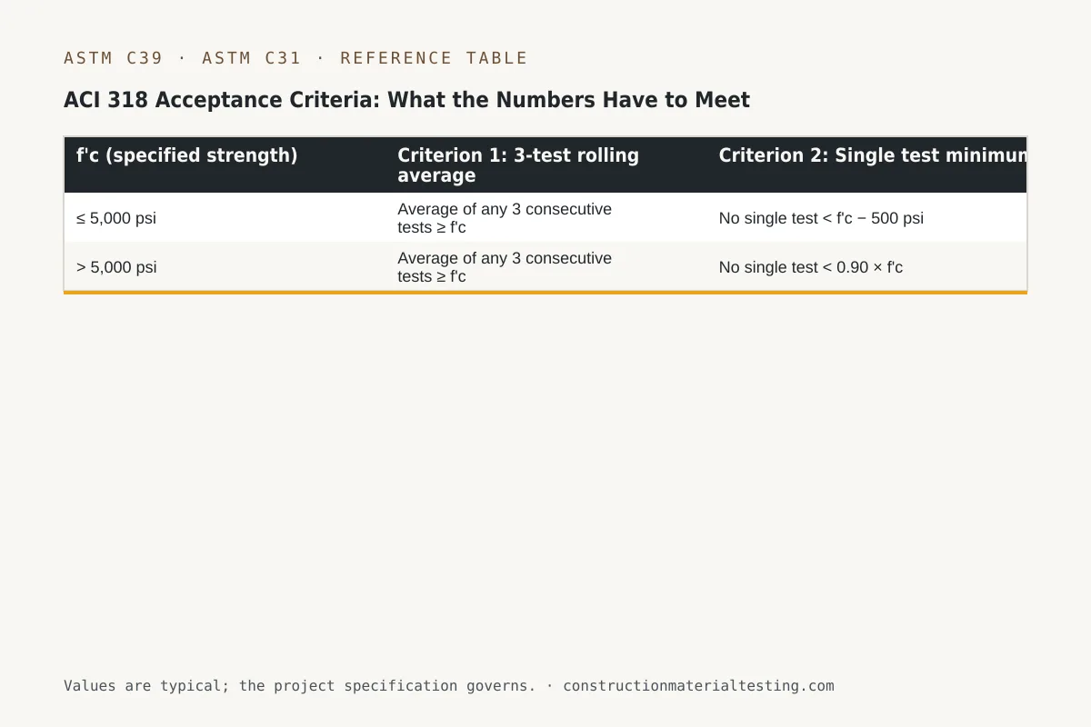
ACI 318—the governing design standard for structural concrete in the United States, published by the American Concrete Institute—establishes the acceptance criteria that determine whether a concrete placement meets its specified strength. There are two simultaneous requirements, both of which must be satisfied.
First, the average compressive strength of any three consecutive strength test results must equal or exceed f'c. A strength test result, as defined in ACI 318, is the average of the two cylinders tested from the same sample at the same age (typically 28 days). If only one cylinder from a set is tested, that single result is the strength test. Projects that cast two cylinders per set and test both are the norm in structural work.
Second, no individual strength test result may fall below f'c by more than 500 psi when f'c is 5,000 psi or less. When f'c is greater than 5,000 psi, the limit shifts—no individual test may fall below 0.90 × f'c. Both criteria must be met simultaneously. A single low test does not automatically mean the concrete is structurally deficient; it triggers an investigation process. The distinction between a failing acceptance criterion and actual structural inadequacy is important and often misunderstood by project stakeholders who see a low number and assume the worst.
Test frequency matters too. ACI 318 requires at least one strength test for each day's pour of each mix design, and at least one for every 150 cubic yards placed, every 5,000 square feet of slab or wall surface, or for each truck if volume is very small. The specifying engineer may require more frequent sampling. Sparse sampling means fewer data points to satisfy the rolling average criterion, which increases the statistical exposure of any single low break.
| f'c (specified strength) | Criterion 1: 3-test rolling average | Criterion 2: Single test minimum |
|---|---|---|
| ≤ 5,000 psi | Average of any 3 consecutive tests ≥ f'c | No single test < f'c − 500 psi |
| > 5,000 psi | Average of any 3 consecutive tests ≥ f'c | No single test < 0.90 × f'c |
Common Reasons Breaks Come Back Low
When a cylinder breaks below the acceptance threshold, the first question is whether the problem is with the cylinder or with the concrete. These are different problems with different consequences, and separating them requires a systematic look at the chain of custody from batching through testing.
Cylinder-side problems are common and include: improper initial curing temperature (too hot or too cold), vibration damage during transport, delayed transport to the laboratory, wet capping material that dilutes the cylinder end, worn or out-of-spec unbonded pads, and a testing machine in need of calibration verification. If the 7-day companion cylinder broke at a percentage of 28-day strength that is lower than expected for the mix design, or if the fracture pattern was anomalous, those are additional signals that the cylinder rather than the concrete may be at fault.
Concrete-side problems include: higher-than-specified water-cement ratio from water added at the truck, inadequate cement content, aggregate proportioning outside the approved mix design, batch plant scale errors, or extended haul times that caused slump loss and prompted water additions in the field. Reviewing the batch tickets for the placement in question—water content, w/cm ratio, admixture dosages, truck revolutions, discharge time—can confirm or rule out these causes.
Environmental factors during placement also matter. Concrete placed in extreme heat (above 95°F ambient in direct sun) may lose workability before it can be properly consolidated, and the water additions that result raise the w/c ratio and reduce strength. Cold weather placements where the concrete in the forms was not adequately protected from freezing can produce severely damaged concrete whose cylinders—stored properly in the lab—actually overestimate the in-place strength. This inversion of the usual relationship is one reason field-cured companion cylinders are sometimes specified alongside standard-cured cylinders: field-cured cylinders track what the in-place concrete actually experienced.
Low-Strength Investigation: Steps Before Any Structural Decision
ACI 318 does not require immediate removal of concrete when a strength test fails acceptance criteria. It establishes a defined investigation path. The process begins with verifying the laboratory data: was the cylinder properly identified, transported, cured, capped, and loaded at the correct rate? Was the machine in calibration? Was the fracture pattern consistent with a valid test? If anything in that chain is questionable, the 28-day companion cylinder from the same set should be tested immediately if it has not been already.
If the data is valid and the result is still low, the next step under ACI 318 is typically to evaluate the in-place concrete itself. ASTM C42 governs the extraction and testing of drilled cores. ACI 318 provides that concrete in an area represented by low-strength test results may be considered structurally adequate if three cores drilled from that area have an average compressive strength of at least 85 percent of f'c, with no individual core below 75 percent of f'c. The location, diameter, and length-to-diameter ratio of the cores matter; ASTM C42 specifies all of these. Cores with embedded reinforcement crossing the test section, significant voids, or other anomalies may need to be discarded and replaced.
Core results that meet the ACI 318 benchmark essentially close the investigation—the in-place concrete is adequate even though the acceptance test failed. Core results that do not meet the benchmark do not automatically condemn the structure; they indicate that a licensed structural engineer must evaluate whether the as-built strength is sufficient for the design loads in that member, potentially with load testing, analysis, or post-installed strengthening. That evaluation is well outside the scope of the testing laboratory's role. Our job is to produce accurate, well-documented data; the structural engineer makes the adequacy determination.
Throughout the investigation, communication matters as much as the technical steps. The project owner, engineer of record, general contractor, and ready-mix supplier should all receive copies of low-strength reports promptly, along with a clear statement of what is known, what is not yet known, and what the next investigative step is. Delays in notification allow work to continue over potentially inadequate concrete, which complicates any later remediation.
Test Age, Mix Design, and Interpreting Early Breaks
The 28-day test age is the contractual compliance age in most specifications because that is when ordinary portland cement concrete reaches approximately 90 to 95 percent of its long-term design strength under standard curing conditions. Mix designs using supplementary cementitious materials—particularly high-volume slag or Class F fly ash replacements—gain strength more slowly and may reach only 70 to 80 percent of 28-day strength at 7 days. Comparing a 7-day result against a 28-day f'c is therefore not valid; it requires using the projected strength gain curve for that specific mix design.
Some specifications write f'c at 56 days for mass concrete or for mixes with high SCM replacement percentages, explicitly to allow the slower-gaining materials to be evaluated fairly. When the project specification says 56-day compliance, 28-day breaks are informational only. We flag this on every report so that a low 28-day result on a 56-day-spec mix is not misread as a failing result.
High-early-strength mixes using Type III cement or accelerating admixtures frequently reach 28-day equivalent strength in 7 days or less. These mixes can complicate interpretation in the opposite direction: a strong 7-day break may lead the contractor to assume all is well, while the 28-day result—if the mix overheated during hydration—can come back lower than expected. We note w/cm ratio and mix type on every test report to give context to the numbers.
| Cement / Binder Type | Typical 7-Day / 28-Day Ratio | Common Compliance Age |
|---|---|---|
| Type I/II OPC (no SCM) | 65–75% | 28 days |
| Type III (high-early) | 80–90% | 7 or 28 days |
| 30–40% Class C fly ash blend | 60–70% | 28 days |
| 50% GGBFS (slag) blend | 50–65% | 28 or 56 days |
| 40% Class F fly ash blend | 45–60% | 28 or 56 days |
Documentation, Chain of Custody, and Report Requirements
Every concrete compression test report we issue traces the cylinder from the point of sampling through final break. ASTM C39 and ASTM C31 together prescribe the minimum information that must appear: project name, concrete supplier and truck ticket number, placement location and element, sample time, concrete temperature, air temperature, slump, air content, unit weight, cylinder identification numbers, mold size, initial curing method and temperature log, standard curing temperature record, test date and age, cross-sectional area, maximum load, compressive strength, fracture pattern type, and type of end preparation used.
Chain-of-custody documentation is the safeguard that allows any dispute over a low result to be investigated rationally. If a cylinder arrives at the laboratory without proper identification, or if the initial curing temperature log shows the cylinders sat at 95°F for the first 12 hours, those facts are documented and disclosed. We do not suppress anomalous data; we flag it and let the engineer evaluate it. A test result that is known to have been compromised by field handling is still useful information—it tells the team what not to trust.
Electronic delivery of test reports through our project portal typically occurs within 24 hours of testing for Houston-metro projects; regional dispatch hub turnaround times depend on the hub's proximity to the laboratory. Regardless of delivery timing, any result that triggers an acceptance failure under ACI 318 is communicated by phone to the project engineer of record before the written report is finalized. That notification protocol is part of our quality system.
Where the Concrete Compression Test Fits on Your Project
Whether the project is a tilt-wall industrial building, a post-tensioned parking structure, or a cast-in-place high-rise core wall, the concrete compression test is the continuous thread connecting the mix design to the as-built structure. Getting the cylinders made correctly under ASTM C31, tested correctly under ASTM C39, with end preparation that meets ASTM C1231 or the applicable capping standard, and with a clear investigation path through ASTM C42 cores if results are low—that sequence is what a well-run special inspection program provides.
If you are setting up a testing and special inspection program for an upcoming concrete scope, or if you have low-strength results on a current project and need to determine the next step, contact our team through the proposal request form. We dispatch ACI-certified field technicians from 27 regional hubs across the region and process cylinder breaks in our Sugar Land laboratory under a documented quality system.
Get our guides in your Google results
Add Construction Materials Testing as a preferred source and Google shows our guides more often when you search for testing topics.