
What the compressive strength test concrete procedure is actually measuring
When a concrete cylinder goes into the compression machine, what we are measuring is the uniaxial load at which the specimen fails divided by its cross-sectional area. The result—expressed in psi or MPa—tells the structural engineer whether the placed concrete has reached the design compressive strength, f'c, that ACI 318 uses as the basis for every load and capacity calculation in the building code. That single number carries real structural weight, which is why ASTM C39 governs every step from how fast you apply the load to how you classify the crack that forms at failure.
What the test does not measure directly is the in-place strength of the structure. Cylinders are standard-cured under controlled temperature and moisture conditions per ASTM C31, which means they represent the potential strength of the mix—not what a particular wall or slab contains after variable field curing. That distinction matters when a 28-day break comes in low and the engineer has to decide whether the structure is actually deficient or whether field curing diverged from standard conditions.
The test is deceptively simple in concept: apply a compressive load at a controlled rate until the cylinder breaks, record the maximum load, calculate the area, divide. In practice, the specimen prep, end condition, alignment, and loading rate all introduce error if they are not controlled. This guide walks through the procedure in the order we actually perform it—field sampling, curing transport, capping, breaking, and interpreting results against the acceptance criteria in ACI 318.
Sampling and curing: what happens before the cylinder reaches the lab
Strength testing starts at the truck or pump discharge, not at the compression machine. Cylinders are made in the field per ASTM C31, consolidated by rodding or vibration depending on slump, struck off flush, and capped with plastic lids. Initial curing is the piece most often mishandled: for the first 24 hours (up to 48 in some specifications), cylinders must be maintained at 60–80 °F and protected from vibration, direct sunlight, and moisture loss. Leaving freshly cast cylinders in the back of a pickup on a hot Texas afternoon, or worse, dropping them while moving them the next morning, creates defects that no lab procedure can correct.
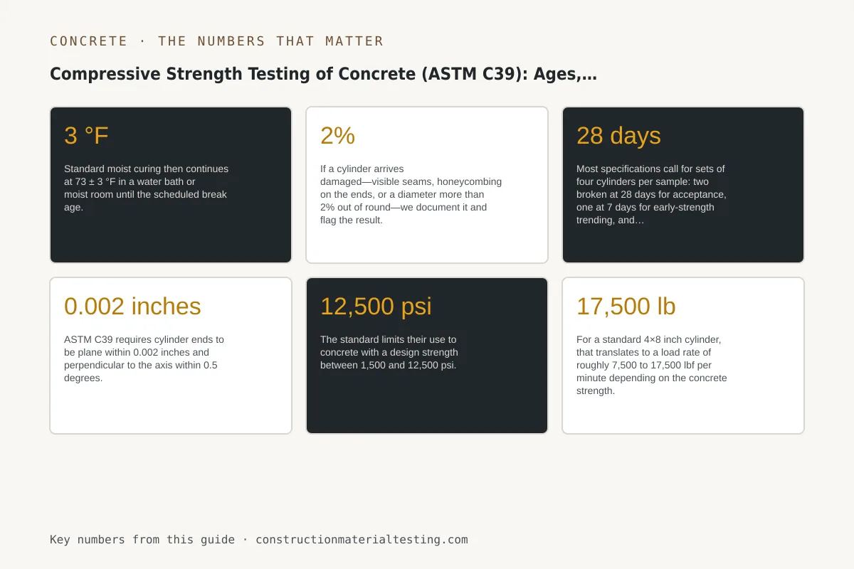
Transport to the laboratory requires padding and upright orientation. Once specimens arrive, we strip them, measure diameter at mid-height in two perpendicular directions, check for end planeness, and log them into our chain-of-custody system. Standard moist curing then continues at 73 ± 3 °F in a water bath or moist room until the scheduled break age. If a cylinder arrives damaged—visible seams, honeycombing on the ends, or a diameter more than 2% out of round—we document it and flag the result. A bad cylinder produces a bad number regardless of how well the break is run.
Break ages and what each one tells you

Most specifications call for sets of four cylinders per sample: two broken at 28 days for acceptance, one at 7 days for early-strength trending, and one held in reserve. Some high-early-strength mixes or precast operations add a 1-day or 3-day break. The table below shows typical break ages and their purpose.
The 7-day result is not an acceptance break. It is an early indicator. Conventional portland cement concrete typically reaches 65–70% of its 28-day strength at 7 days under standard curing, so a rough projection is possible, but mix design, SCM content, water-to-cementitious ratio, and temperature all shift that ratio. We use 7-day results to flag mixes that are tracking low so the contractor and engineer can prepare—not to declare a failure. Acceptance decisions rest on 28-day cylinders unless the project specification explicitly designates a different age.
When a project uses high-strength concrete or performance-based specifications, a 56-day break is sometimes the acceptance criterion. In those cases the 28-day break becomes the early indicator. Whatever the specified age, only the designated acceptance cylinders drive the ACI 318 evaluation. Breaking a hold cylinder early to resolve a dispute is an option, but doing so uses up the only remaining specimen from that sample, so it should be a deliberate decision made with the engineer of record.
| Break Age | Typical Purpose | Typical % of 28-day f'c (OPC mix) | Acceptance Break? |
|---|---|---|---|
| 1 day | Precast form-strip evaluation | 20–40% | Only if specified |
| 3 day | Early-strength verification | 40–60% | Only if specified |
| 7 day | Trending indicator | 65–75% | No |
| 28 day | Standard acceptance | 100% (baseline) | Yes (default) |
| 56 day | High-strength / SCM-heavy mixes | 105–115% | Only if specified |
Capping and end preparation: why the bearing surface matters
ASTM C39 requires cylinder ends to be plane within 0.002 inches and perpendicular to the axis within 0.5 degrees. An out-of-plane end concentrates stress at high points and produces an artificially low—and highly variable—result. End preparation options are sulfur mortar capping, grinding, or unbonded neoprene pad systems. Each has a defined application range.
Unbonded neoprene caps per ASTM C1231 are the most common choice in general structural work because they are reusable and fast. They consist of a neoprene pad retained in a steel retainer ring. The standard limits their use to concrete with a design strength between 1,500 and 12,500 psi. Below 1,500 psi the pad is too stiff relative to the concrete and introduces end restraint errors; above 12,500 psi the pad compresses unevenly and underestimates strength. Pad durometers and retainer dimensions are specified in ASTM C1231, and pads must be inspected and replaced when they show permanent deformation, cracking, or surface gouging. Using a worn pad is one of the more common sources of scatter in reported results.
Sulfur mortar capping bonds directly to the cylinder ends and is the traditional method for high-strength concrete or when C1231 limits are exceeded. It requires careful temperature control during application—too cool and the cap bonds poorly; too hot and it flows instead of setting—and a minimum cure period before testing. Grinding is the most geometrically reliable option but requires equipment, adds time, and removes aggregate that can influence surface-layer behavior. Our ASTM C39 procedure specifies which end preparation we apply based on the specified f'c noted on the mix design submittal.
Loading rate and fracture type classification
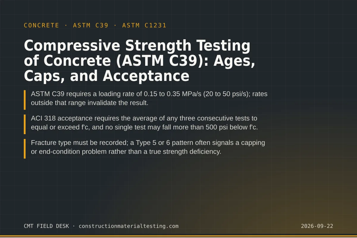
ASTM C39 requires the load to be applied continuously and without shock at a rate that produces a stress increase of 0.15 to 0.35 MPa/s (approximately 20 to 50 psi/s) during the final phase of loading. For a standard 4×8 inch cylinder, that translates to a load rate of roughly 7,500 to 17,500 lbf per minute depending on the concrete strength. Machines that run open-loop or are poorly calibrated can apply load too fast, which artificially elevates the result, or too slowly, which can allow creep effects and underestimate strength. Rate verification is part of our equipment calibration program.
At failure, the technician observes and records the fracture pattern. ASTM C39 defines six fracture types. Type 1 is a well-formed cone on one end—the textbook result for a well-prepared cylinder with uniform stress distribution. Type 2 is a cone on one end with vertical cracks through the opposite end. Type 3 is a columnar failure with vertical cracks through both ends with no well-formed cones. Type 4 is a diagonal shear with no cracking through the ends. Type 5 is a side fracture at the top or bottom—almost always a capping or alignment problem. Type 6 is a similar side fracture but at mid-height.
Types 1 through 4 are considered normal fractures and the result stands as reported. Types 5 and 6 warrant investigation of the end preparation and machine alignment before the result is used for acceptance decisions. A string of Type 5 failures on a project is a technician or equipment problem, not necessarily a concrete problem, and tracking fracture type is how we catch it early. We record fracture type on every break report because an engineer reviewing a borderline result needs that context.
ACI 318 acceptance criteria for compressive strength test concrete results
ACI 318 defines a strength test as the average of at least two cylinders made from the same sample of concrete and tested at the same age. The acceptance standard has two simultaneous requirements. First, the average of any three consecutive strength tests must equal or exceed the specified f'c. Second, no individual strength test (the two-cylinder average) may fall more than 500 psi below f'c. Both conditions must be satisfied; meeting one while failing the other is still a non-conformance. The ACI 318 Building Code provisions for this are found in the chapter on evaluation and acceptance of concrete.
The 500-psi single-test tolerance exists because concrete strength has inherent statistical variability. A mix designed to 4,000 psi will have individual test results that scatter around that mean. The tolerance is not a buffer to be consumed routinely—it is a recognition that a single low result may reflect sampling variability rather than a deficient batch. When multiple consecutive tests trend low or when a single result falls more than 500 psi below f'c, the engineer is required to evaluate the structural adequacy of the affected portion of the work. That evaluation can range from additional testing (cores per ASTM C42, load tests) to analysis, to remediation.
Contractors sometimes treat a low 7-day result as a trigger for the 500-psi evaluation. It is not—that evaluation applies only to acceptance-age breaks. What a low 7-day result should trigger is a conversation with the engineer, a review of field curing logs, and a plan for what happens if the 28-day result confirms the trend. Catching that situation at 7 days gives the project team three weeks to prepare; catching it at 28 days on a pour that has already been loaded eliminates most of the good options. Our materials testing services include reporting structured to surface those trends before the acceptance date.
When results fail acceptance, the project specification and ACI 318 both contain investigation procedures. The engineer of record drives that process. Our role is to provide accurate break data, complete fracture type records, and curing logs so that the investigation starts with good information rather than gaps. Understanding the cost structure of construction materials testing ahead of time also helps owners plan for the possibility of supplemental testing without schedule disruption.
Where this fits on your project
Compressive strength testing is a continuous obligation across every concrete placement, not a one-time checkpoint. The frequency of sampling, the break ages required, and the acceptance threshold are all defined by the project specification and the applicable building code—typically IBC Section 1705 for special inspection requirements. Our dispatch hubs across 27 regional locations mean a certified technician is available to sample at the point of placement and our laboratory processes breaks on a schedule tied to the specified acceptance ages.
If you are setting up a concrete testing program for a new project or reviewing results from one already underway, we are equipped to help structure the sampling plan, interpret borderline results, and coordinate with the engineer of record on investigation procedures when they are needed. Request a proposal and describe the mix design, specified f'c, and placement schedule so we can match technician availability and lab capacity to your pour sequence from the start.
Get our guides in your Google results
Add Construction Materials Testing as a preferred source and Google shows our guides more often when you search for testing topics.